

Fine geomechanics modeling and in-situ stress simulation around the well
-
摘要: 陆相页岩油岩性纵横向变化较快,纹层、夹层发育,非均质性强。以往针对五峰−龙马溪组等深层页岩气攻关的地质力学研究多以区域性建模预测为主,建模网格较粗,缺乏对储层纵向的精细刻画,不适用于非均质性较强的陆相地层。此外,水力裂缝、天然裂缝与地应力之间的相互影响关系需要进一步明确,压裂成缝的关键因素需要进一步厘清。为应对陆相页岩储层非均质性较强的问题,该研究旨在建立适用于陆相页岩的井周精细地质力学模型,以预测井周应力场的分布和局部应力扰动特征,进一步分析断裂、裂缝、构造样式对井周应力扰动的影响。将该方法应用于川东南复兴地区陆相页岩储层评价,结果表明:纵向上,凉高山组陆相页岩储层顶底高应力砂岩层发育,对压裂裂缝的纵向扩展存在一定影响,而⑥号小层内部应力较为均一,该小层中部是水平井轨迹最佳穿行层位;平面上,裂缝发育会导致局部应力方向发生偏转且应力值降低,当裂缝走向与最大主应力方向夹角为45°时,应力扰动最为显著。建模预测结果为水平井轨迹方位优选、靶窗确定及工程施工提供重要参考依据。Abstract:
Objective Continental shale oil reservoirs show rapid lithological variations, abundant laminae and interbeds, and strong heterogeneity, so that conventional regional geomechanical models with coarse grids, originally developed for relatively homogeneous deep marine shale gas reservoirs, cannot finely characterize vertical stress partitioning or capture local stress perturbations around wells. In the Jurassic Lianggaoshan Formation of the Fuxing area in the southeastern Sichuan Basin, the lack of high-resolution near-wellbore stress characterization and of a clear understanding of how faults and natural fractures disturb the in-situ stress field limits the design of horizontal well trajectories and hydraulic fracturing schemes. This study aims to establish a refined near-wellbore geomechanical modeling and in-situ stress simulation workflow for strongly heterogeneous continental shale reservoirs and to clarify the vertical and planar in-situ stress characteristics of the Lianggaoshan Formation, thereby identifying favorable landing intervals and azimuths for horizontal wells. Methods Focusing on a near-wellbore area with a radius of about 4 km, a refined geological grid model with a vertical resolution of 0.5–2.0 m was constructed and combined with high-resolution seismic inversion trend volumes to perform trend-constrained co-simulation of well-log-derived mechanical parameters, thus generating a high-precision three-dimensional geomechanical property model. On this basis, a nested finite element modeling strategy was adopted: a regional model provided the six-component background in-situ stress field, which was used as the initial stress condition in the near-wellbore model, where the effects of faults and fractures represented by an extended finite element method-based fracture–stress coupling scheme were simulated to predict near-wellbore stress distributions and local stress disturbances. Results (1) The refined near-wellbore geomechanical model significantly improves the vertical resolution and reliability of stress prediction in continental shale reservoirs: compared with directly assigning seismic inversion results to finite element grids, trend-constrained co-simulation yields mechanical property models that better honor lithologic layering and well-log measurements and that reduce noise in the predicted minimum principal stress. (2) For the Lianggaoshan Formation in the Fuxing area, the modeling results show that high-stress sandstone layers are developed at the top and base of the target sub-member ⑥, where the minimum principal stress is about 10–13 MPa higher than in the internal mudstone, forming vertical stress barriers that hinder the upward and downward propagation of hydraulic fractures; in contrast, the stress inside sub-member ⑥ is relatively uniform, with vertical stress differences generally less than 5 MPa, providing a continuous interval suitable for horizontal well landing. (3) Parametric simulations of single fractures at a burial depth of about 2800 m indicate that local stress disturbances around a fracture are strongly controlled by fracture orientation: for vertical fractures, the maximum stress disturbance is obtained when the fracture strike forms an angle of approximately 45° with the maximum horizontal principal stress; as the fracture strike tends to be parallel or perpendicular to the maximum horizontal stress, the disturbance decreases, and for a given strike angle, the disturbance increases with fracture dip and reaches its maximum at a dip of 90°, reflecting the stress-shadow effect of fractures. (4) Near-wellbore fracture–stress coupling simulations around representative wells confirm that the development of faults and fracture swarms causes local rotation and reduction of the horizontal principal stresses relative to the regional NE–SW maximum horizontal stress direction, and that hydraulic fractures preferentially propagate along low-stress corridors created by these fracture zones, thereby explaining the observed spatial distribution of stimulation in the Fuxing area. Conclusion The proposed workflow, which combines trend-constrained co-simulation of mechanical parameters with regional–local nested finite element stress modeling and fracture–stress coupling analysis, can effectively capture multi-scale heterogeneity and near-wellbore stress perturbations in continental shale reservoirs and provides a more realistic prediction of vertical stress partitioning and local stress disturbances than conventional regional models; for the Lianggaoshan Formation, the results demonstrate that high-stress sandstone layers at the top and base of sub-member ⑥ have a non-negligible impact on the vertical extension of hydraulic fractures, whereas the relatively uniform stress within the interior of sub-member ⑥ makes its middle part the optimal interval for horizontal well landing, while in the plane, natural fracture zones cause local rotation of the maximum horizontal stress direction and reduce stress magnitudes, which can either promote or limit the growth and complexity of hydraulic fractures depending on their strike and intensity. Significance This study develops a practical fine near-wellbore geomechanical modeling and stress simulation technology suitable for strongly heterogeneous continental shale reservoirs, clarifies the vertical and planar in-situ stress characteristics and their controlling mechanisms in the Lianggaoshan continental shale of the Fuxing area, and provides an important scientific basis for optimizing horizontal well landing intervals, wellbore azimuths, and fracturing design in similar continental shale oil and gas plays. -
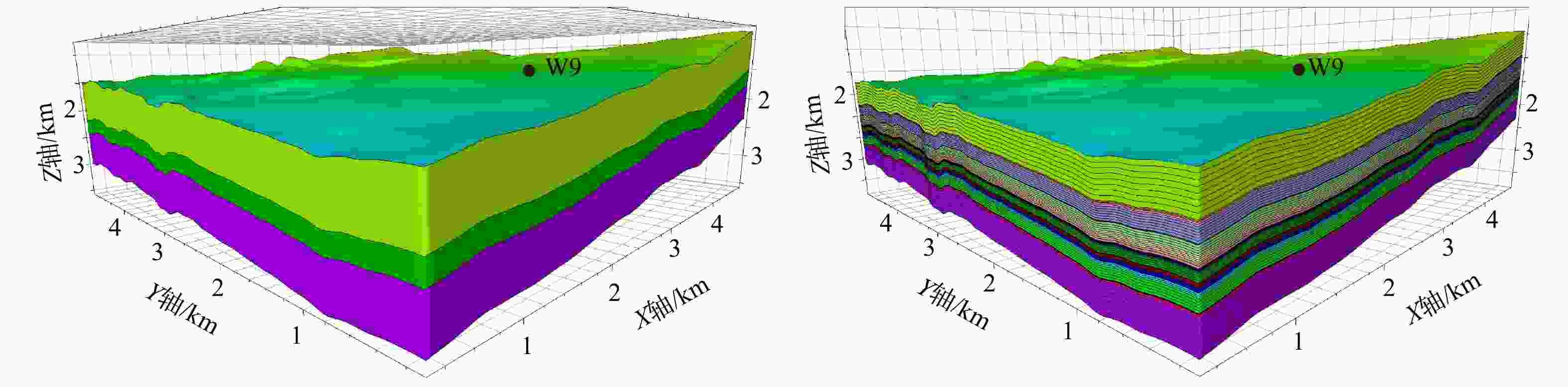
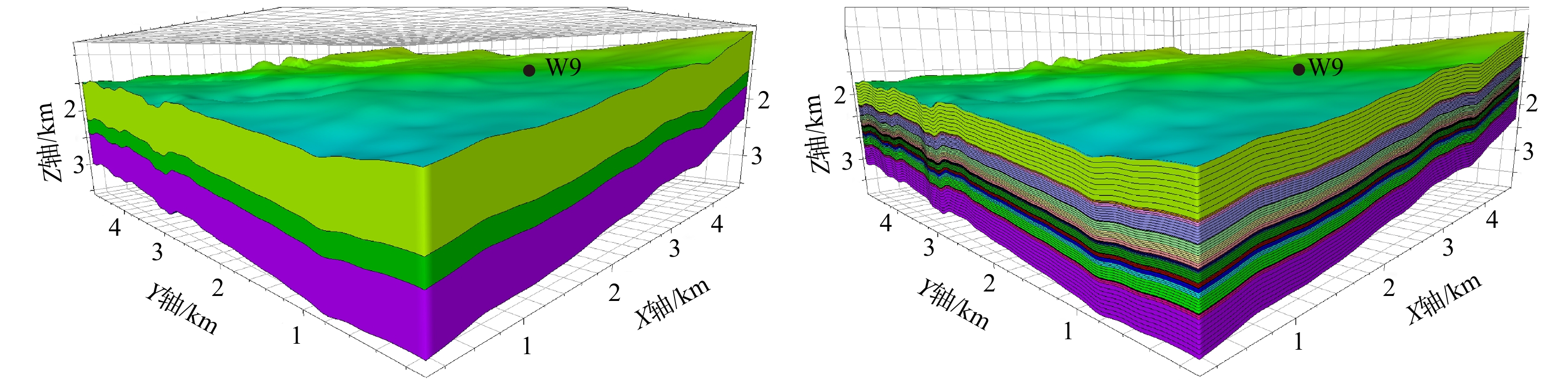
图 1 区域模型与井周精细格架模型对比图(储层部分)
黑点为W9井所在模型中的位置;Z轴为向下递增a—大型区域地质力学格架模型;b—井周局部精细格架模型
Figure 1. Comparison of regional grid model and refined near-wellbore grid model (reservoir section)
(a) Large-scale regional geomechanical grid model; (b) Refined local near-wellbore grid modelThe black dot indicates the location of Well W9 in the model; the Z-axis increases downward.
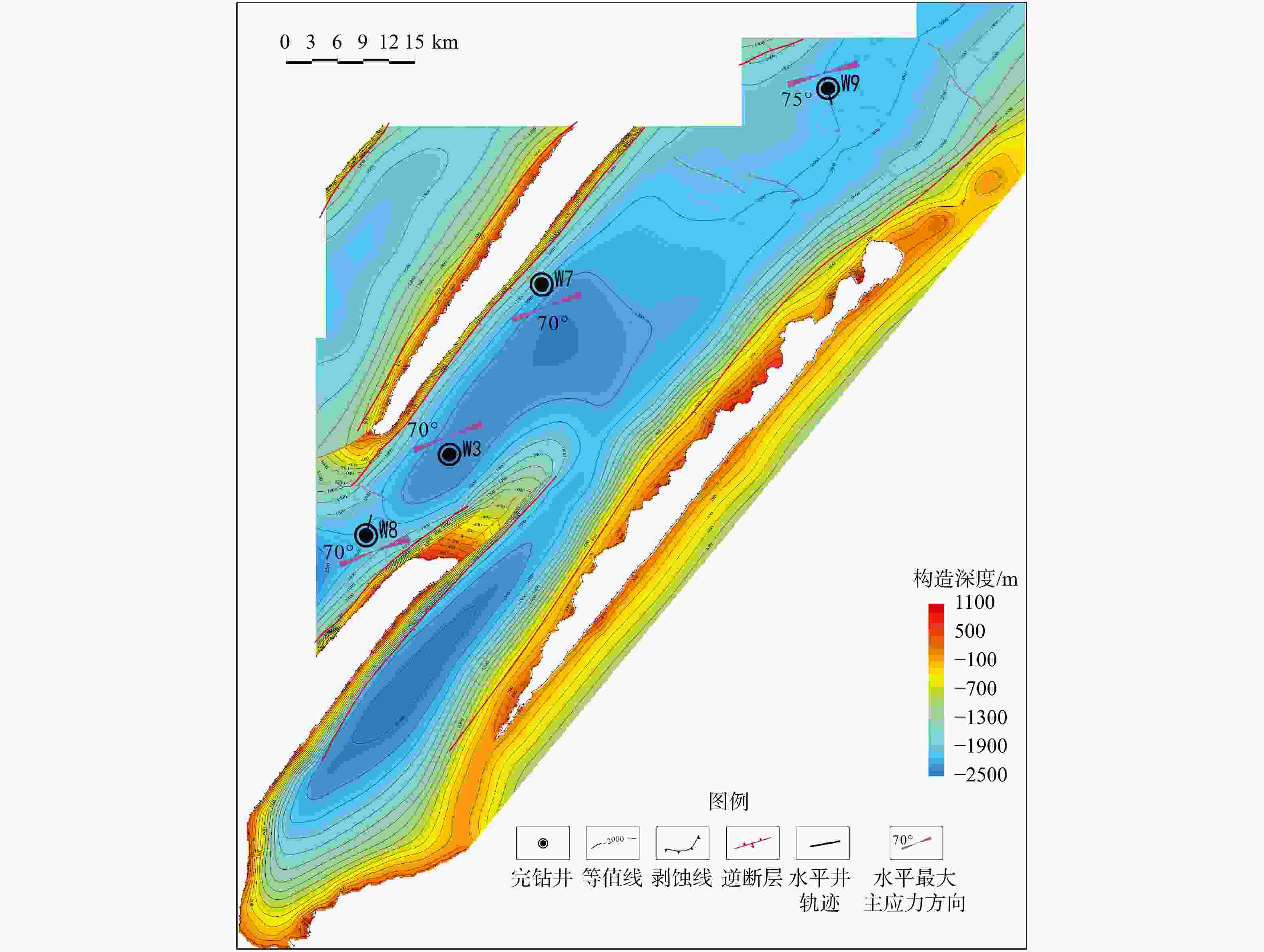
图 2 研究区凉高山组底界构造及主要井最大主应力方向图
Figure 2. Structural contour map of the bottom boundary of the Lianggaoshan Formation and the maximum principal stress orientations in major wells of the study area
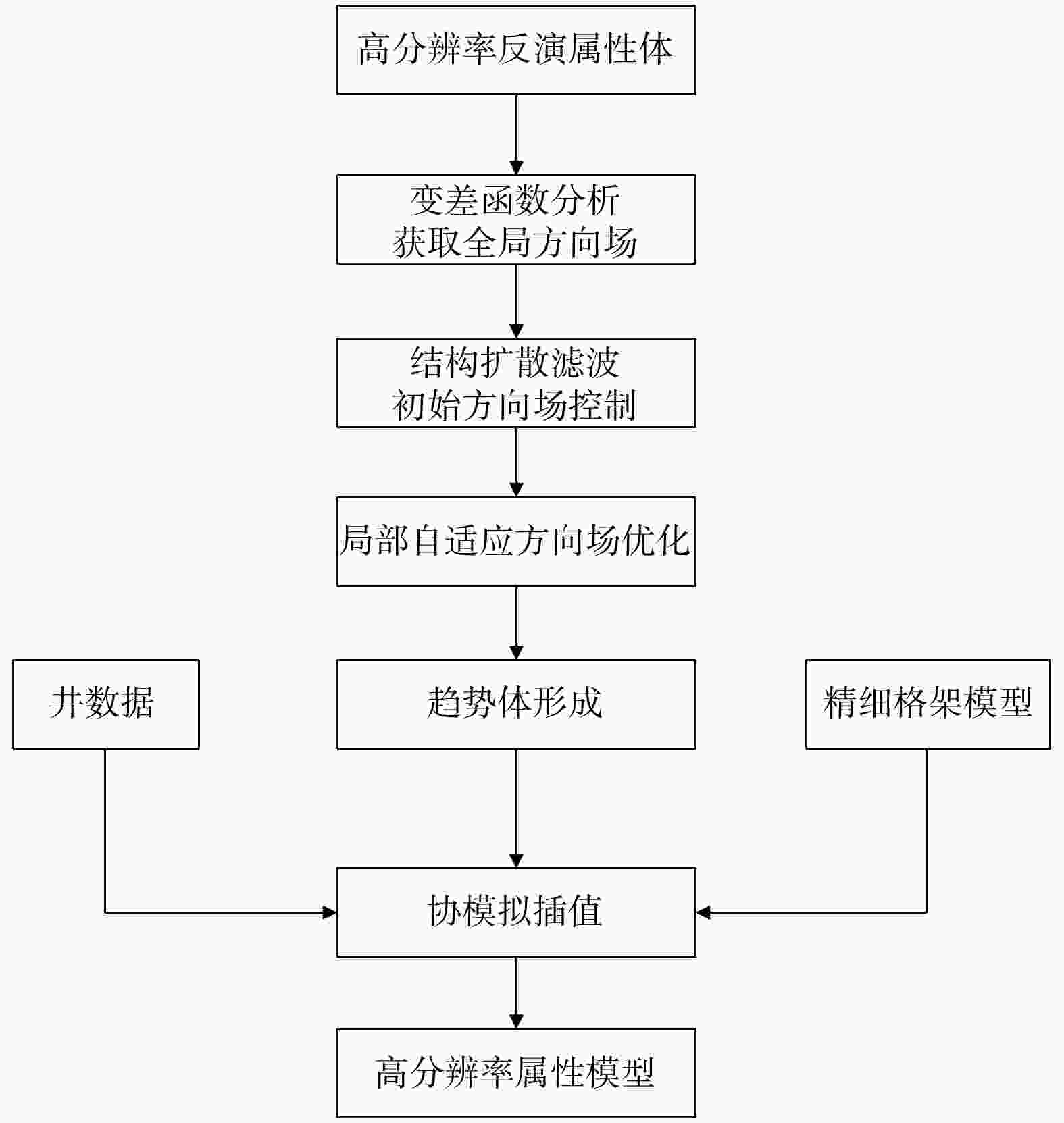
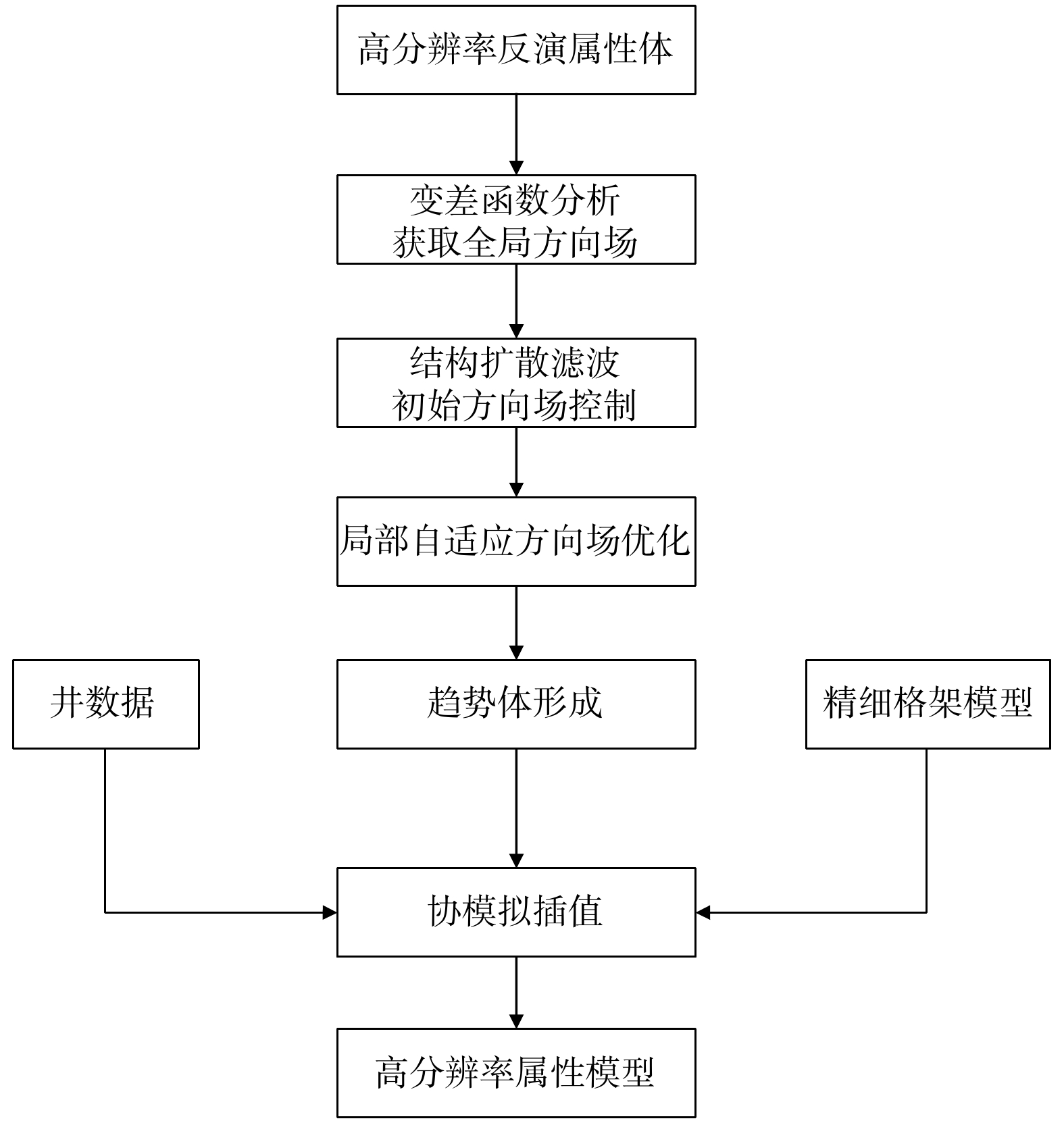
图 3 井周高精度地质建模流程图
Figure 3. Flowchart of High-precision near-wellbore geological modeling
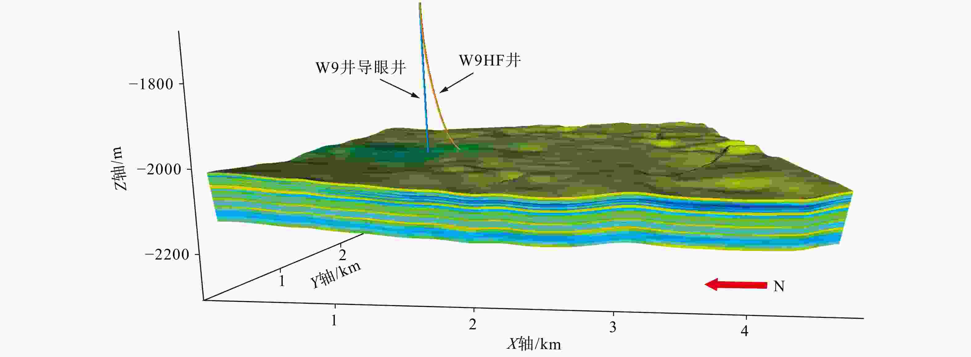
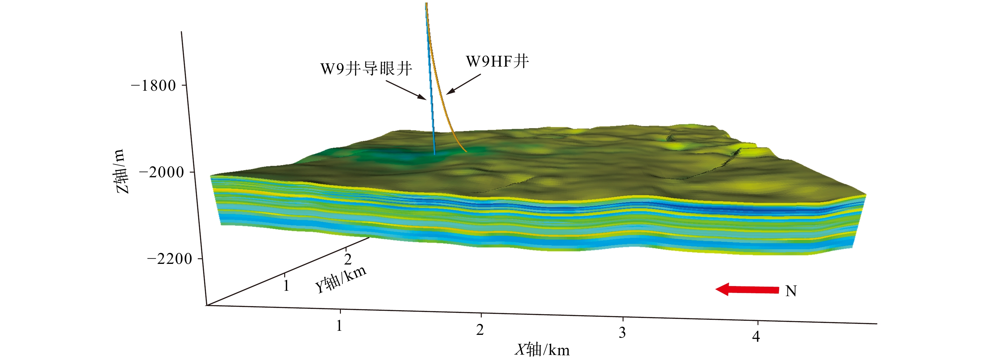
图 4 井周高分辨率地质建模立体图(储层部分)
W9HF井为W9井同井场用于水力压裂的水平井
Figure 4. High-resolution near-wellbore geological modeling 3D diagram (reservoir section)
Well W9HF is a horizontal well located at the same pad as Well W9, used for hydraulic fracturing.

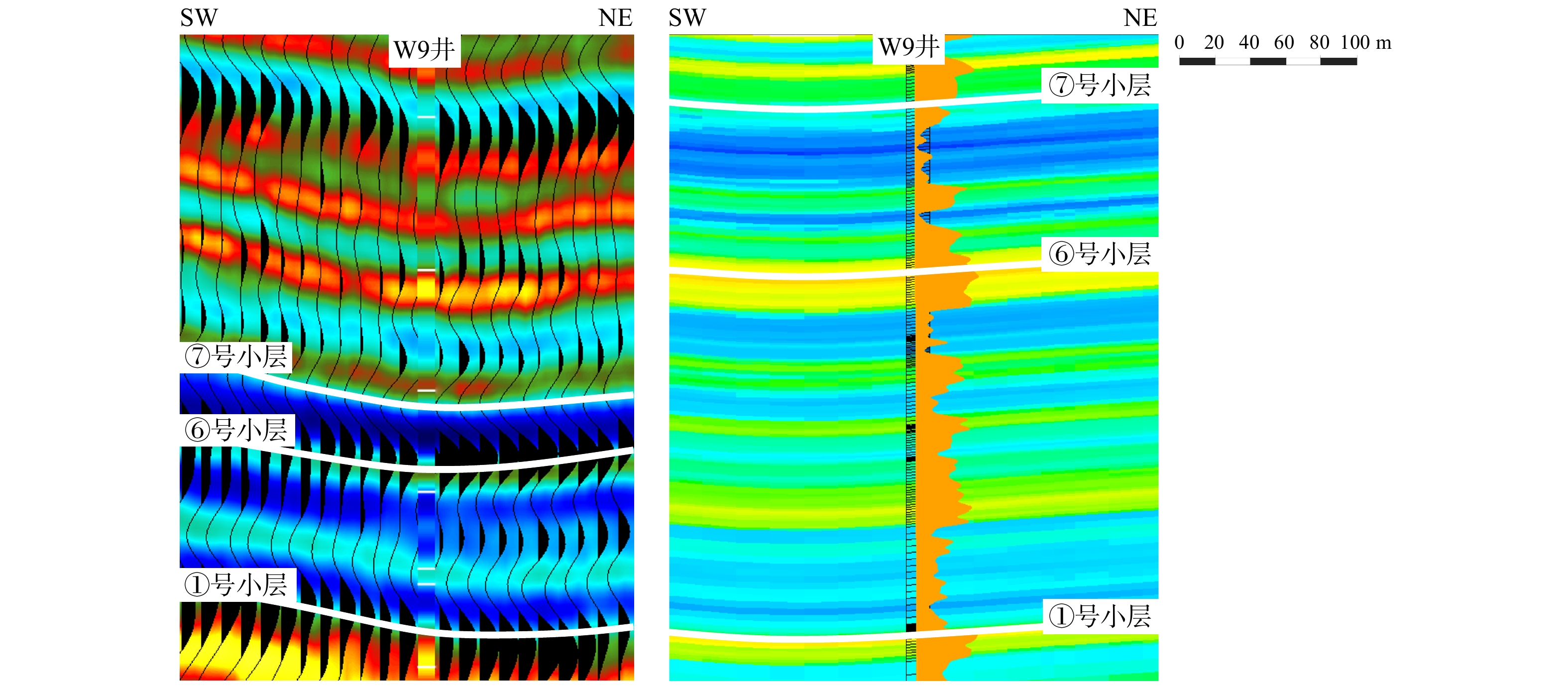
图 5 高分辨率阻抗反演结果与井周高精度阻抗建模对比图
a—高分辨率阻抗反演结果;b—井周高精度阻抗建模结果
Figure 5. Comparison between high-resolution impedance inversion result and high-precision near-wellbore impedance modeling
(a) High-resolution impedance inversion result; (b) High-precision near-wellbore impedance modeling result
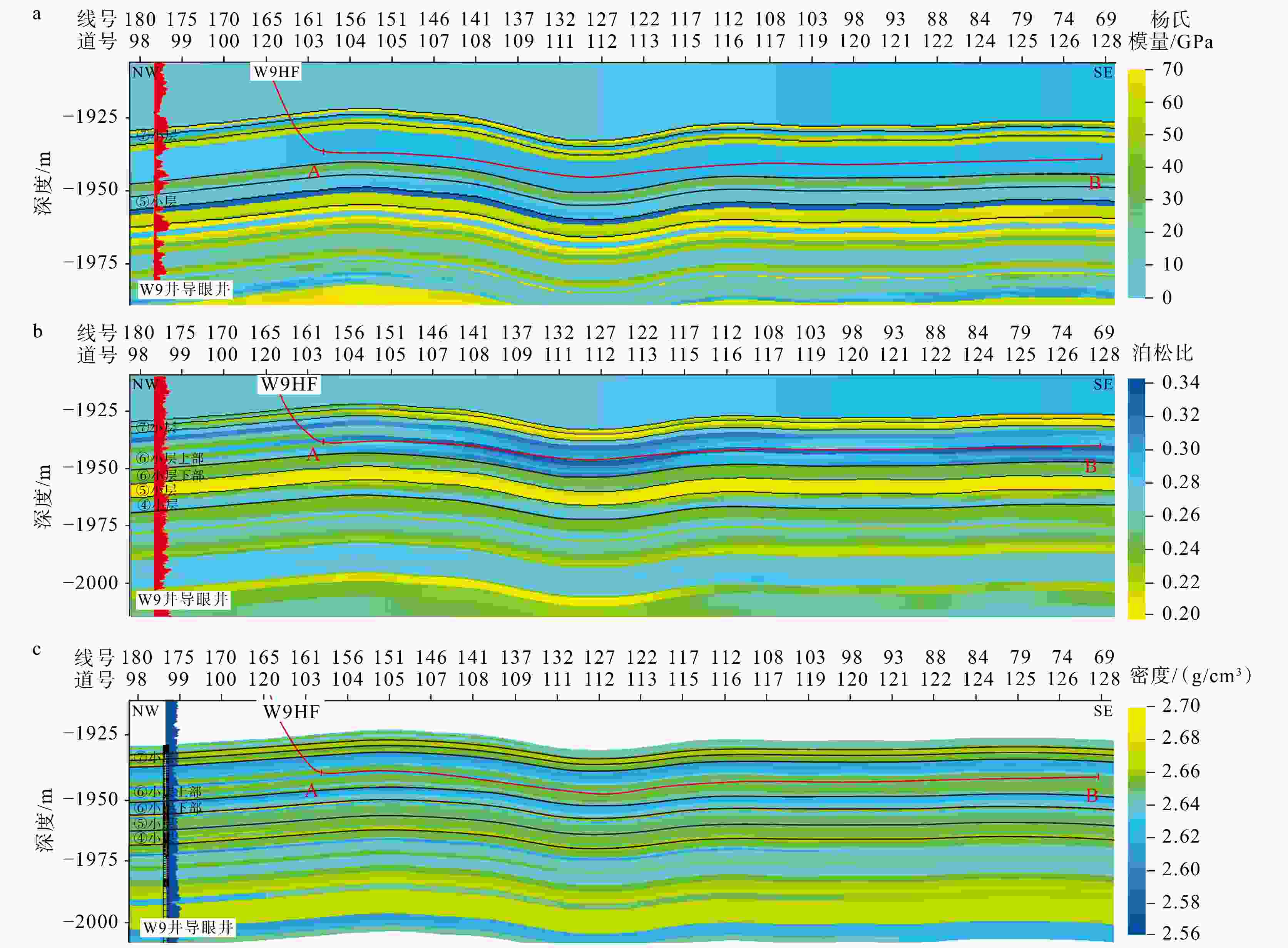
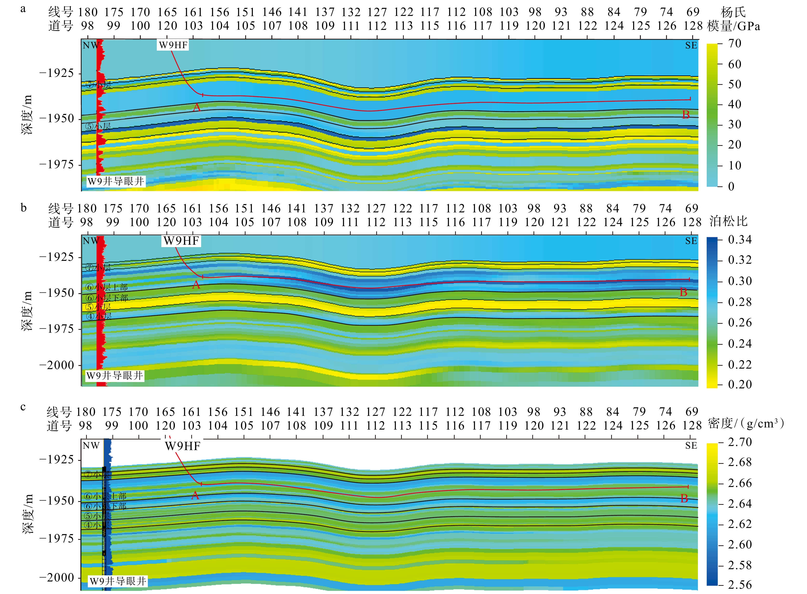
图 6 井周高分辨率力学参数模型
层间黑线为小层底界线;A、B为水平井A、B靶点;线号、道号间隔为20 ma—杨氏模量;b—泊松比;c—密度
Figure 6. High-resolution near-wellbore mechanical parameter models
(a) Young's modulus; (b) Poisson's ratio; (c) Density The interlayer black lines represent the bottom boundaries of the sub-layers; A and B represent the toe and heel targets of the horizontal well, respectively; Both the line interval and trace interval are 20 m.
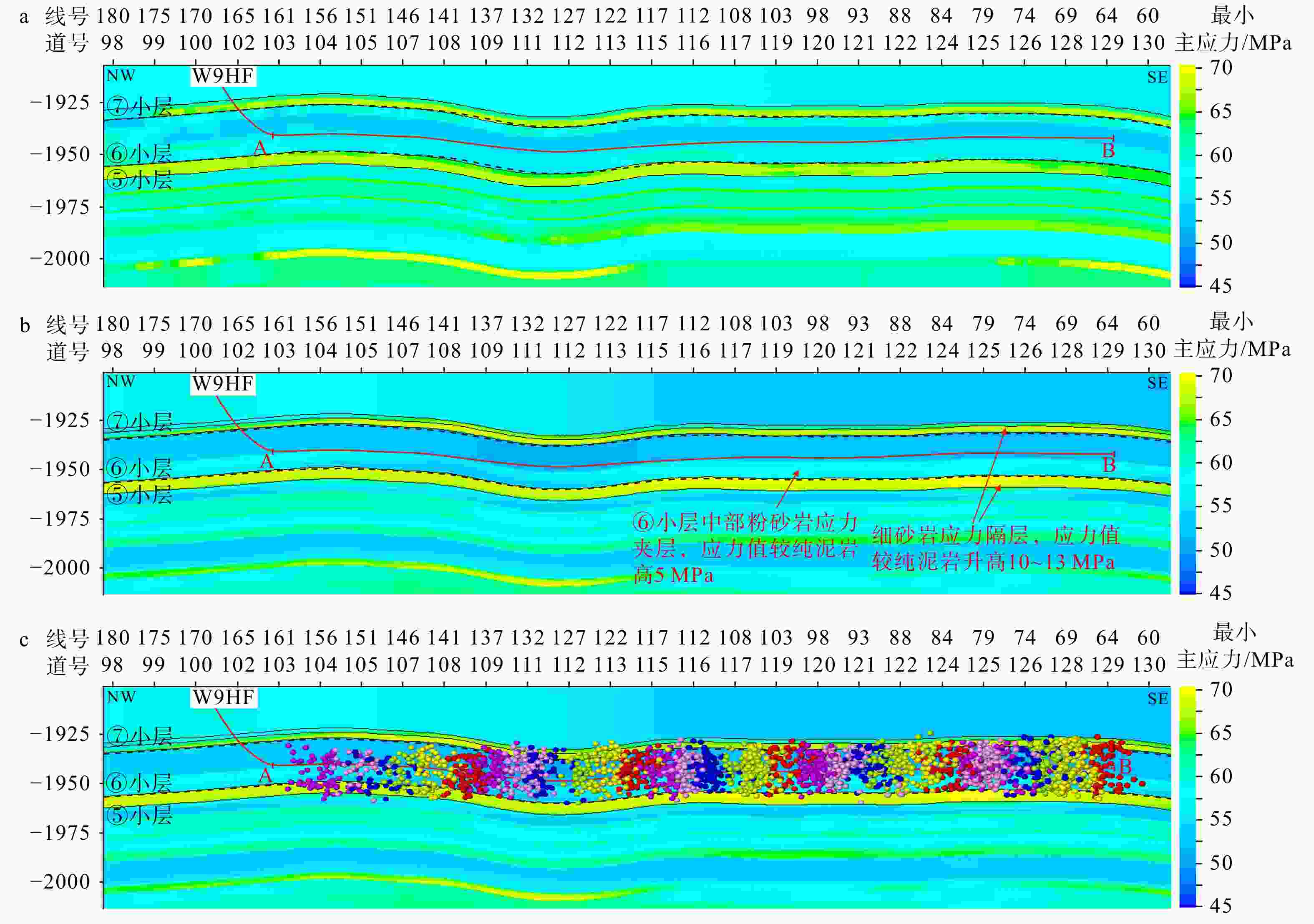
图 7 过W9HF井最小水平主应力预测剖面图
A、B为水平井A、B靶点;彩球为水平井压裂的微地震事件;层间黑线为小层底界线;黑色虚线为靶窗顶、底界;线号、道号间隔为20 ma—高分辨率反演直接赋值法有限元模拟最小主应力剖面;b—井周精细地质建模有限元模拟最小主应力剖面;c—井周精细地质建模有限元模拟最小主应力剖面叠加微地震事件
Figure 7. Predicted minimum horizontal principal stress profile along W9HF
(a) Minimum principal stress profile from finite element simulation using high-resolution inversion direct assignment; (b) Minimum principal stress profile from finite element simulation using refined near-wellbore geological modeling; (c) Minimum principal stress profile from finite element simulation using refined near-wellbore geological modeling with superimposed microseismic events A and B represent the toe and heel targets of the horizontal well, respectively; The colored spheres denote the microseismic events induced by the hydraulic fracturing of the horizontal well; The black lines between layers represent the bottom boundaries of sub-layers; The black dashed lines indicate the top and bottom boundaries of the target window; Both the line interval and trace interval are 20 m.
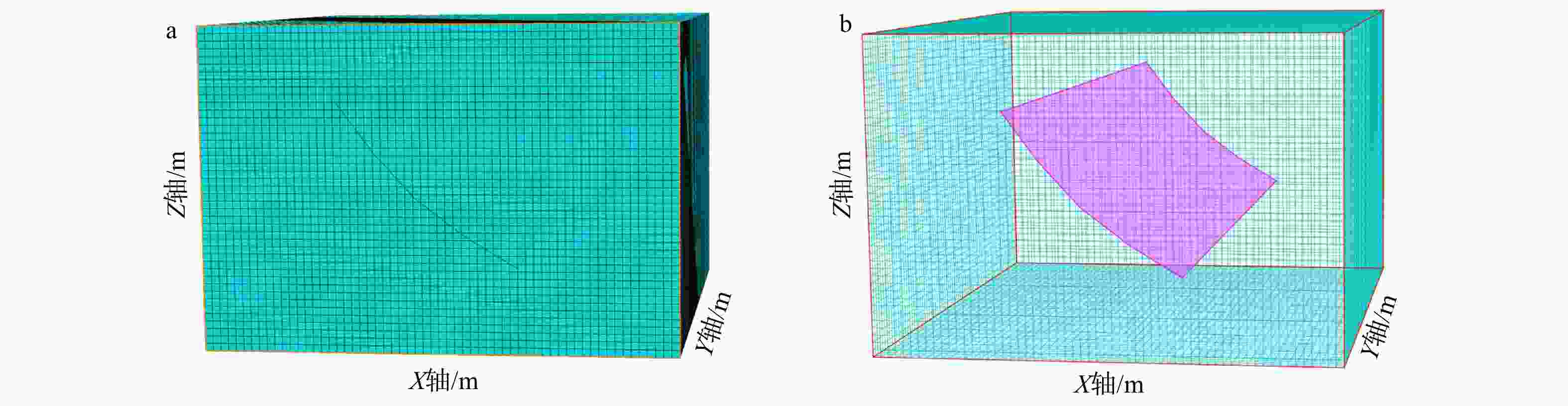
图 8 扩展有限元法裂缝模型
模型尺寸为300 m×215 m×200 m;网格尺寸为5 m×5 m ×5 m a—材料分类显示;b—镂空显示
Figure 8. XFEM (Extended Finite Element Method) fracture model
(a) Material classification view; (b) Cutaway view The model dimensions are 300 m × 215 m × 200 m, with a grid cell size of 5 m × 5 m × 5 m.
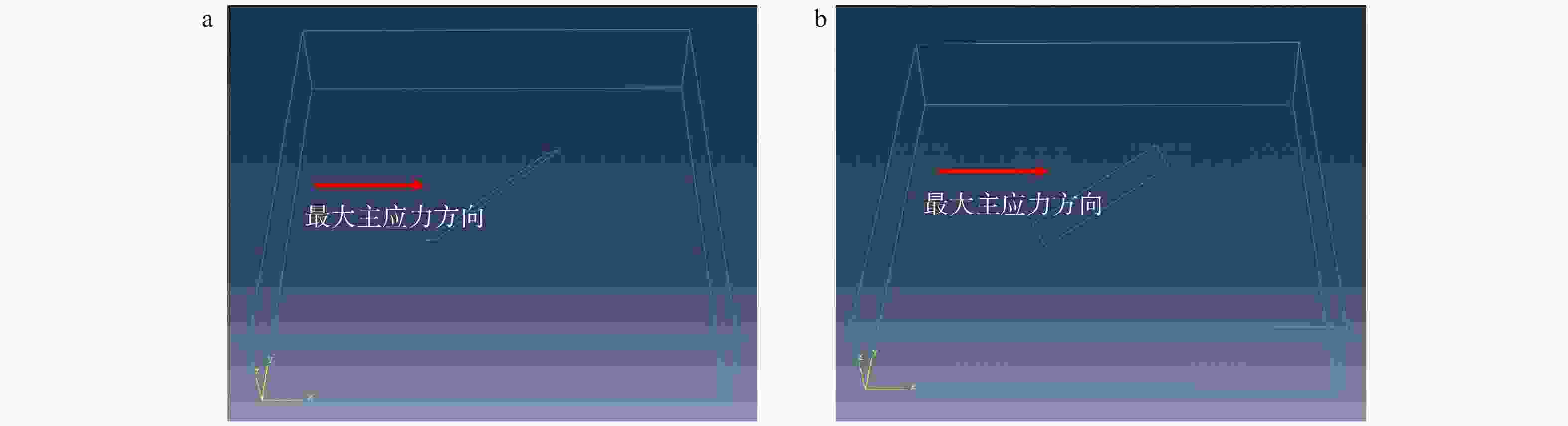
图 9 部分单裂缝空间模型图
a—走向45°、倾角45°的裂缝模型;b—走向45°、倾角0°的裂缝模型
Figure 9. Partial 3D models of single fractures
(a) Fracture model with 45º strike and 45º dip; (b) Fracture model with 45º strike and 0º dip
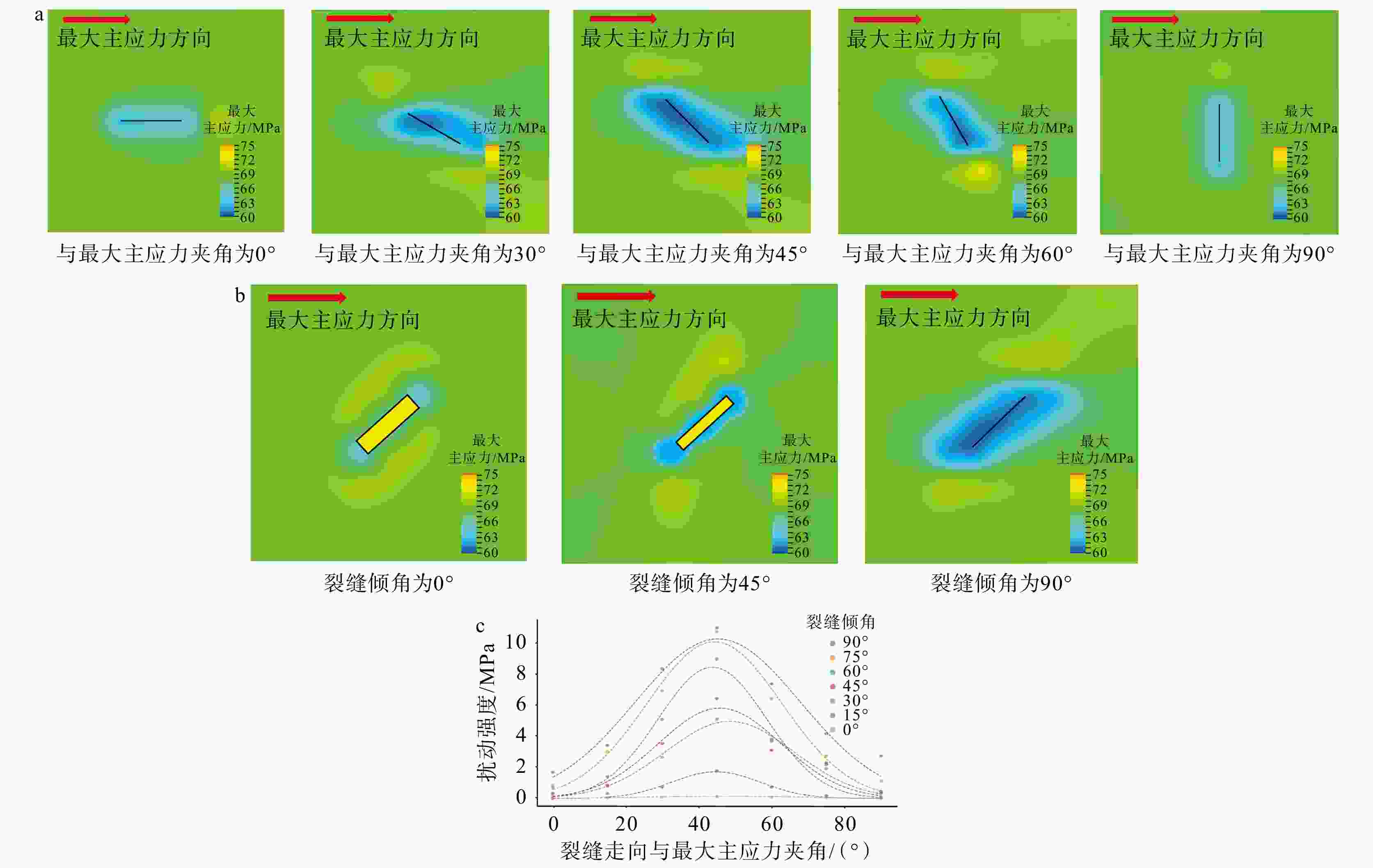
图 10 单裂缝模型裂缝产状对应力扰动的影响图
a— 裂缝走向对地应力影响模拟;b— 裂缝倾角对地应力影响模拟;c—不同倾角、不同夹角裂缝对地应力扰动强度的影响
Figure 10. Effects of fracture orientation on stress disturbance in single-fracture models
(a) Simulation of the effect of fracture strike on in-situ stress; (b) Simulation of the effect of fracture dip on in-situ stress; (c) Influence of fractures with different dips and intersection angles on the intensity of stress disturbance
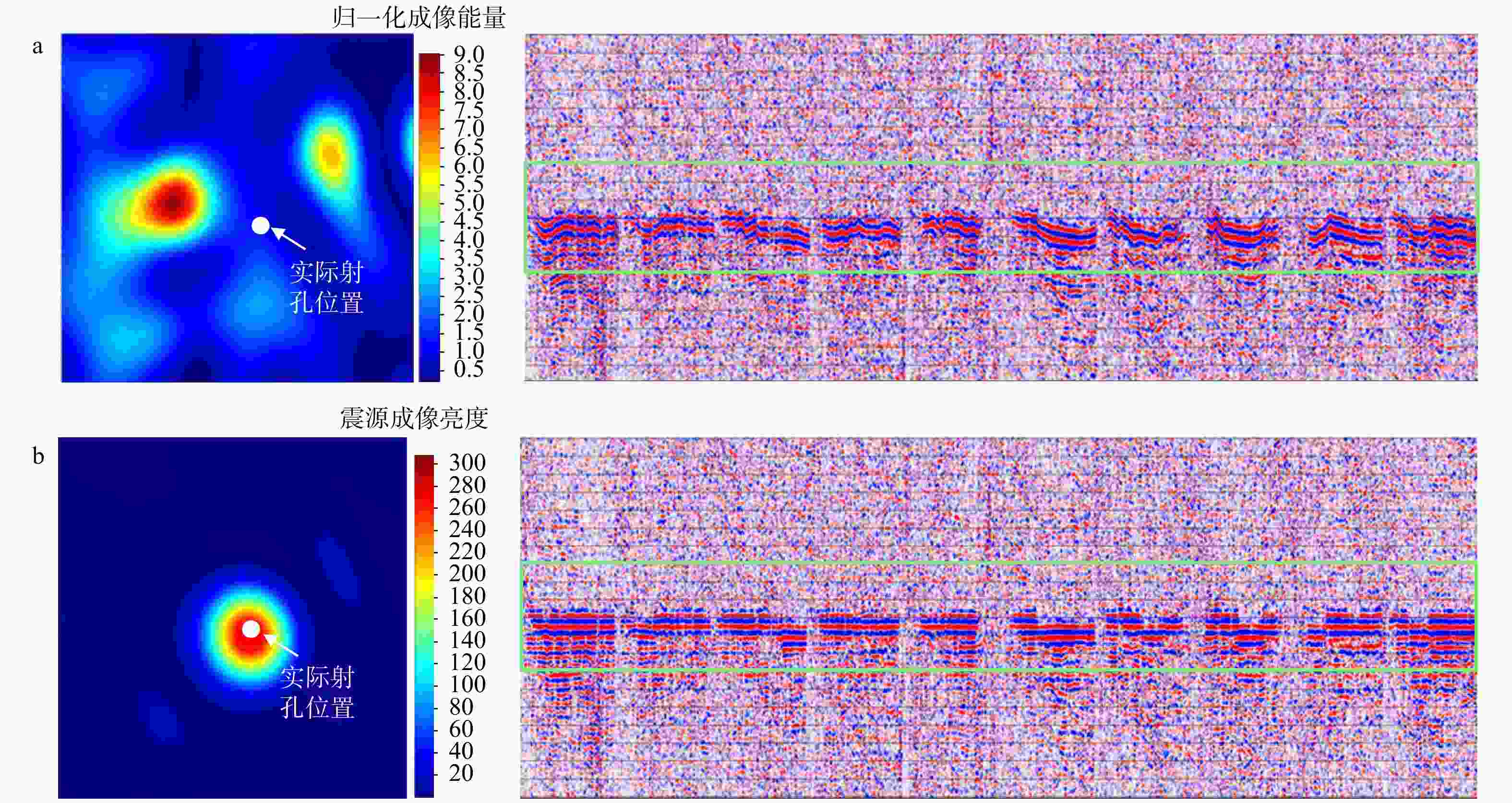
图 11 静校正前后射孔信号的定位对比图
a—静校正前射孔信号定位;b—静校正后射孔信号定位
Figure 11. Comparison of shot-point location before and after static correction
(a) Before static correction; (b) After static correction
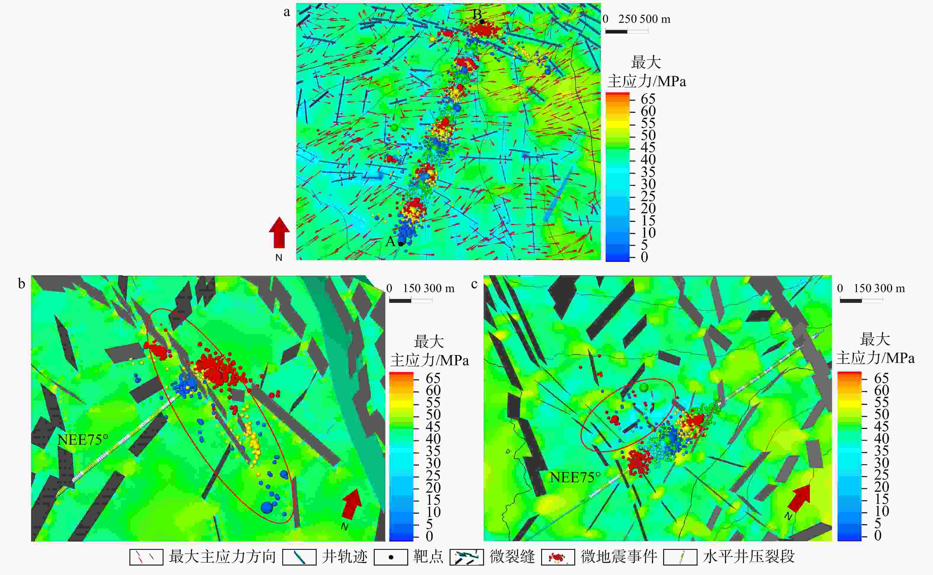
图 12 W8井井周力缝耦合地应力模拟图
a—W8井整体压裂模型;b—W8井前三段压裂模型;c—W8井15—19段压裂模型
Figure 12. Near-wellbore stress simulation of fracture-stress coupling for W8
(a) Overall fracturing model of W8; (b) Fracturing model of the first three stages in W8; (c) Fracturing model of stages 15–19 in W8
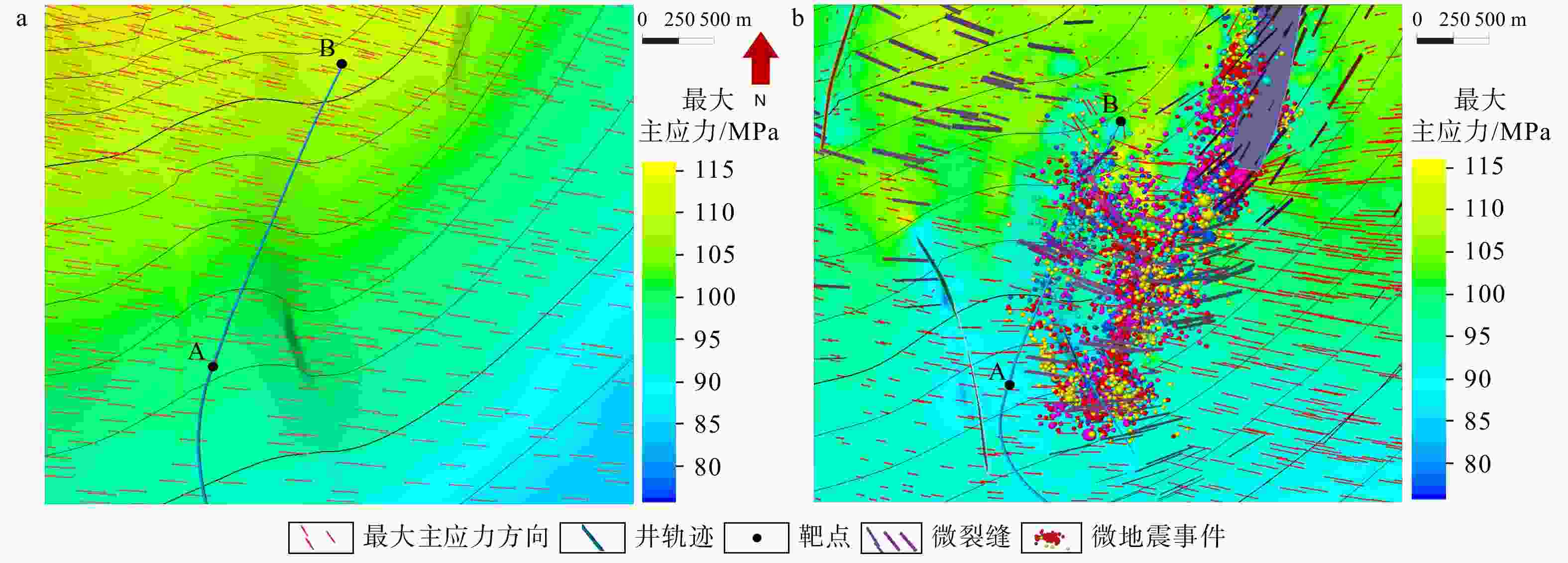
图 13 W11井井周力缝耦合地应力模拟结果图
a—区域初始应力场(井周部分);b—力缝耦合井周二次迭代应力场
Figure 13. Simulation results of fracture–stress coupling and in-situ stress around W11
(a) Regional initial stress field (near-wellbore section); (b) Secondary iteration of near-wellbore stress field after fracture–stress coupling
表 1 趋势体方向场权重参数分档与默认值
Table 1. Classification and default parameters of directional weighting factors for trend volume
SNR α β $ {\boldsymbol{\omega }}_{\mathbf{m}\mathbf{i}\mathbf{n}} $ 建议说明 备注 低(SNR≤3) 0.5 0.4 0.3 提高全局权重,抑制噪声方向 必要时上调α至0.6 中(3<SNR≤6) 0.4 0.4 0.2 全局−局部折中,地震数据缺少SNR评估时使用该方案 可作为通用默认 高(SNR>6) 0.3 0.5 0.2 增强局部权重,保留细节 避免过拟合,设上限$ {\omega }_{g} $≤0.8  下载: 导出CSV
-
[1] BELYTSCHKO T, GRACIE R, VENTURA G, 2009. A review of extended/generalized finite element methods for material modeling[J]. Modelling and Simulation in Materials Science and Engineering, 17(4): 043001. doi: 10.1088/0965-0393/17/4/043001 [2] CHEN C, CHEN Z Q, LIU X J, et al., 2025. Key technologies for predicting sweet spots of Jurassic Lianggaoshan Formation continental shale oil and gas in the Fuxing area of the Sichuan Basin[J]. Natural Gas Industry, 45(1): 94-104. (in Chinese with English abstract) [3] FENG Q, XU S, ZHANG F, 2016. Research on FEM modeling of in situ stress field and its application to deep well drilling[J]. Petroleum Exploration and Development, 43(1): 158-163. doi: 10.1016/S1876-3804(16)30019-2 [4] FRIES T P, BELYTSCHKO T, 2010. The extended/generalized finite element method: an overview of the method and its applications[J]. International Journal for Numerical Methods in Engineering, 84(3): 253-304. doi: 10.1002/nme.2914 [5] GUO X S, HU D F, HUANG R C, et al., 2020. Deep and ultra-deep natural gas exploration in the Sichuan Basin: progress and prospect[J]. Natural Gas Industry, 40(5): 1-14. (in Chinese with English abstract) [6] HU D F, WEI Z H, WEI X F, et al., 2025. Breakthrough in the exploration of continental shale oil/gas of Jurassic Lianggaoshan Formation in the Fuxing area of the Sichuan Basin and its inspiration[J]. Natural Gas Industry, 45(1): 1-13. (in Chinese with English abstract) [7] HUANG X, WANG Y, WANG Z, 2014. 3D finite element modeling of the stress field in faulted reservoirs[J]. Journal of Petroleum Science and Engineering, 122: 570-581. [8] HUNT L, REYNOLDS S, HADLEY S, et al., 2011. Causal fracture prediction: curvature, stress, and geomechanics[J]. The Leading Edge, 30(11): 1274-1286. doi: 10.1190/1.3663400 [9] JIANG D Q, LI P P, ZOU H Y, 2024. Characteristics of Natural Fractures and Their Influence on Oil and Gas Enrichment and Preservation of the Jurassic Continental Shale in the Yuanba Area, Northeastern Sichuan Basin[J]. Geoscience, 38(2): 362-372. DOI: 10.19657/j.geoscience.1000-8527.2023.065. (in Chinese with English abstract) [10] KIM J, TCHEN D, TCHEN C, 2012. Coupled geomechanical modeling of fracture and stress in tight shale gas reservoirs[J]. SPE Journal, 17(3): 630-642. [11] LI Y L, LIU X G, HU Z M, et al., 2019. Research progress on fracture network simulation in shale reservoirs[J]. Oil Geophysical Prospecting, 54(2): 480-492. (in Chinese with English abstract) [12] MA N, YIN X Y, SUN C Y, et al., 2018a. Inversion for crustal stress based on azimuthal seismic data[J]. Chinese Journal of Geophysics, 61(2): 697-706. (in Chinese with English abstract) [13] MA N, YIN X Y, ZONG Z Y, et al., 2018b. The application of curvature attributes to in-situ stress seismic prediction[J]. Computing Techniques for Geophysical and Geochemical Exploration, 40(2): 182-188. (in Chinese with English abstract) [14] RASHID F, GLOVER P W J, LORINCZI P, et al., 2017. Microstructural controls on reservoir quality in tight oil carbonate reservoir rocks[J]. Journal of Petroleum Science and Engineering, 156: 814-826. doi: 10.1016/j.petrol.2017.06.056 [15] XIE J T, FU X P, QIN Q R, et al., 2022. Prediction of fracture distribution in shale reservoirs in the Dingshan Area and evaluation of shale gas preservation conditions[J]. Special Oil & Gas Reservoirs, 29(1): 1-9. (in Chinese with English abstract) [16] XIONG C H, LIU X J, CHEN C, et al. , 2024. Prediction method of horizontal stress difference based on finite element simulation stress background constraints[C]//Proceedings of the 6th annual conference on oil and gas geophysics. Sanya: Oil and Gas Geophysical Specialty Committee of Chinese Geophysical Society: 288-291, doi: 10.26914/c.cnkihy.2024.041717. (in Chinese with English abstract) [17] 陈超, 陈祖庆, 刘晓晶, 等, 2025. 四川盆地复兴地区侏罗系陆相凉高山组页岩油气甜点预测关键技术[J]. 天然气工业, 45(1): 94-104. doi: 10.3787/j.issn.1000-0976.2025.01.008 [18] 郭旭升, 胡东风, 黄仁春, 等, 2020. 四川盆地深层-超深层天然气勘探进展与展望[J]. 天然气工业, 40(5): 1-14. doi: 10.3787/j.issn.1000-0976.2020.05.001 [19] 胡东风, 魏志红, 魏祥峰, 等, 2025. 四川盆地复兴地区侏罗系凉高山组陆相页岩油气勘探突破及启示[J]. 天然气工业, 45(1): 1-13. doi: 10.3787/j.issn.1000-0976.2025.01.001 [20] 蒋代琴, 李平平, 邹华耀, 2024. 川东北元坝地区侏罗系陆相页岩天然裂缝发育特征及其对页岩油气富集和保存的影响[J].现代地质, 38(02):362-372.DOI: 10.19657/j.geoscience.1000-8527.2023.065. [21] 李亚龙, 刘先贵, 胡志明, 等, 2019. 页岩储层压裂缝网模拟研究进展[J]. 石油地球物理勘探, 54(2): 480-492. doi: 10.13810/j.cnki.issn.1000-7210.2019.02.028 [22] 马妮, 印兴耀, 孙成禹, 等, 2018a. 基于方位地震数据的地应力反演方法[J]. 地球物理学报, 61(2): 697-706. doi: 10.6038/cjg2018L0183 [23] 马妮, 印兴耀, 宗兆云, 等, 2018b. 曲率属性在地应力地震预测中的应用[J]. 物探化探计算技术, 40(2): 182-188. doi: 10.3969/j.issn.1001-1749.2018.02.07 [24] 谢佳彤, 付小平, 秦启荣, 等, 2022. 丁山地区页岩储层裂缝分布预测及页岩气保存条件评价[J]. 特种油气藏, 29(1): 1-9. doi: 10.3969/j.issn.1006-6535.2022.01.001 [25] 熊晨皓, 刘晓晶, 陈超, 等, 2024. 基于有限元模拟应力背景约束的水平应力差预测方法[C]//第六届油气地球物理学术年会论文集. 三亚: 中国地球物理学会油气地球物理专业委员会: 288-291, doi: 10.26914/c.cnkihy.2024.041717. -

 下载:
下载:


计量
- 文章访问数: 308
- HTML全文浏览量: 105
- PDF下载量: 133
- 被引次数: 0
