

Numerical simulation of deformation and stress processes in fault–bend folding: Quantitative constraints based on elastoplastic parameter control
-
摘要: 断层转折褶皱(Fault–Bend Fold)作为褶皱–冲断带的标志性构造样式,不仅是解析挤压构造变形的关键运动学单元,更因断坪–断坡转换带的岩性错位形成构造圈闭,成为前陆盆地油气勘探的重要目标。文章基于Suppe提出的经典理论模型,采用有限元数值模拟方法,建立地质力学模型,赋予实际岩石力学参数,厘定控制断层转折褶皱形成的边界条件,并解析其发育过程中应力–应变分布及变形特征。结合Mohr-Coulomb弹塑性本构模型深入探讨密度($ \rho $)、杨氏模量($ E $)、泊松比($ \upsilon $)、内摩擦角($ \phi $)、黏聚力($ c $)以及剪胀角($ \psi $)6项岩石力学参数对构造变形的控制程度,并提出关键控制因素。主要结论如下:开放边界条件是断层转折褶皱发育的动力学前提,当褶皱前端为开放边界条件时,该条件下滑移过程符合经典几何–运动学模型;而固定边界条件时,前翼因固定边界而向底部产生大幅度的倾斜卷入,整体变形偏离断层转折褶皱几何–运动学模型。断层转折褶皱在变形过程中应力–应变产生显著分区,褶皱两翼和断坡上部表现为挤压区,褶皱核部和断坪上部处于伸展区,2个转折端处不仅可观察到应力集中且沿轴面向上递减现象,同时也表现为塑性应变的发育区,塑性应变沿着断层面向前扩展,产生一系列的剪切变形带;下转折端上方塑性应变带的扩展主导了后翼的构建,作为应变局部化与剪切破裂的起源,上转折端则控制了背斜核部及前翼的发育,形成张性应力场并可能发育裂缝系统。断层转折褶皱的动力学演化机制本质上是岩层在挤压应力作用下为适应先存断层几何形态而发生的递进变形过程,这一过程构成了一个从初始滑动与后翼建造,到前翼生长与褶皱雏形显现,再到稳定滑移与褶皱扩展,并最终以褶皱定型及复杂构造衍生为终点的完整动力学链条。黏聚力和内摩擦角是控制断层转折褶皱变形的关键参数,二者均表现出显著的非线性响应与临界阈值行为;黏聚力参数主要控制褶皱波长变化,内摩擦角参数主要控制褶皱前翼的陡窄程度;而杨氏模量与剪胀角的影响较弱且具局部敏感性;低杨氏模量参数有利于构造形成,剪胀角会使构造略微拓宽。密度参数与泊松比参数则不会产生影响。
-
关键词:
- 断层转折褶皱 /
- Mohr-Coulomb弹塑性本构模型 /
- 应力–应变特征 /
- 构造变形 /
- 有限元数值模拟
Abstract:Objective Fault–bend folds, characteristic structures in fold-and-thrust belts, act as key kinematic units in the analysis of compressional deformation and form structural traps at flat–ramp transitions. This makes them critical targets in the exploration of hydrocarbons in foreland basins. Methods Using Suppe’s theoretical model and finite element simulations, we developed a geomechanical model with realistic rock properties. We defined boundary conditions for fold formation and analyzed stress-strain patterns during the evolution of fault–bend folds. We applied the Mohr-Coulomb model to assess six parameters—density (ρ), Young’s modulus (E), Poisson’s ratio (υ), internal friction angle (ϕ), cohesion (c), and dilation angle (ψ)—for identifying dominant controls. Results Open boundaries enable the development of fault-bend folds consistent with classical models, whereas fixed boundaries cause marked forelimb tilting and non-classical deformation. Stress-strain partitioning is distinct: Fold limbs and the upper ramp experience compression; the core and upper flat undergo extension. Both axial surfaces show upward-decreasing stress concentrations and plastic strain. The lower axial surface builds the backlimb and initiates shear fracturing; the upper axial surface shapes the anticlinal core and forelimb under tension, developing potential fracture systems. Cohesion (c) and the internal friction angle (ϕ) are key factors governing fold wavelength and forelimb steepness, respectively, with nonlinear threshold behaviors. Young’s modulus and dilation angle have localized, minor influence. Density and Poisson’s ratio show negligible effects. Conclusion Fault–bend folding is a progressive deformation process in which strata adjust to adapt to the geometry of pre-existing faults under compressive stress. This results in a kinematic sequence from initial slip and backlimb growth, through fold nucleation and propagation, to final stabilization with complex derived structures. Cohesion and the internal friction angle are the decisive controlling parameters. Significance This numerical analysis clarifies the development mechanisms, stress–strain organization, and controlling factors of fault–bend folds, deepening the theoretical understanding of compressional tectonic deformation. -
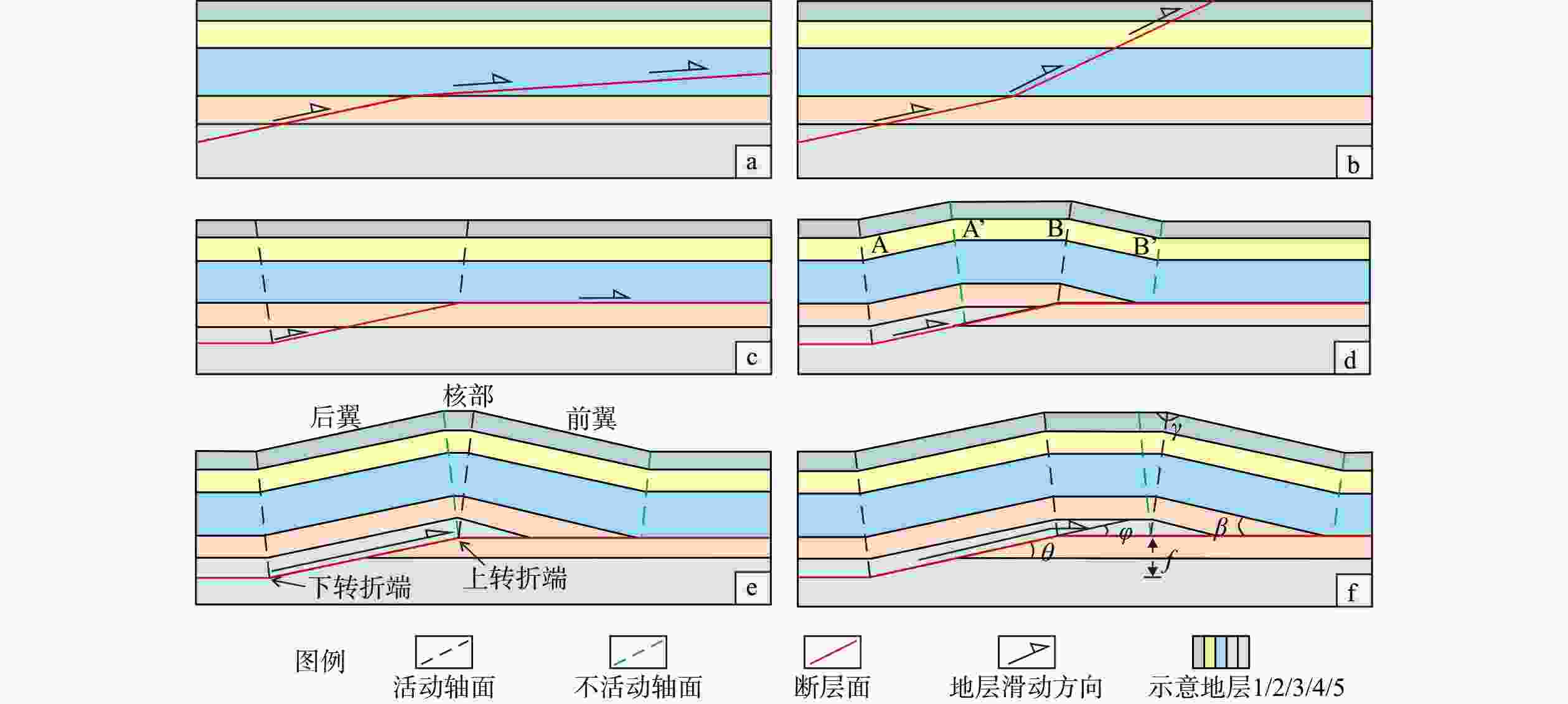
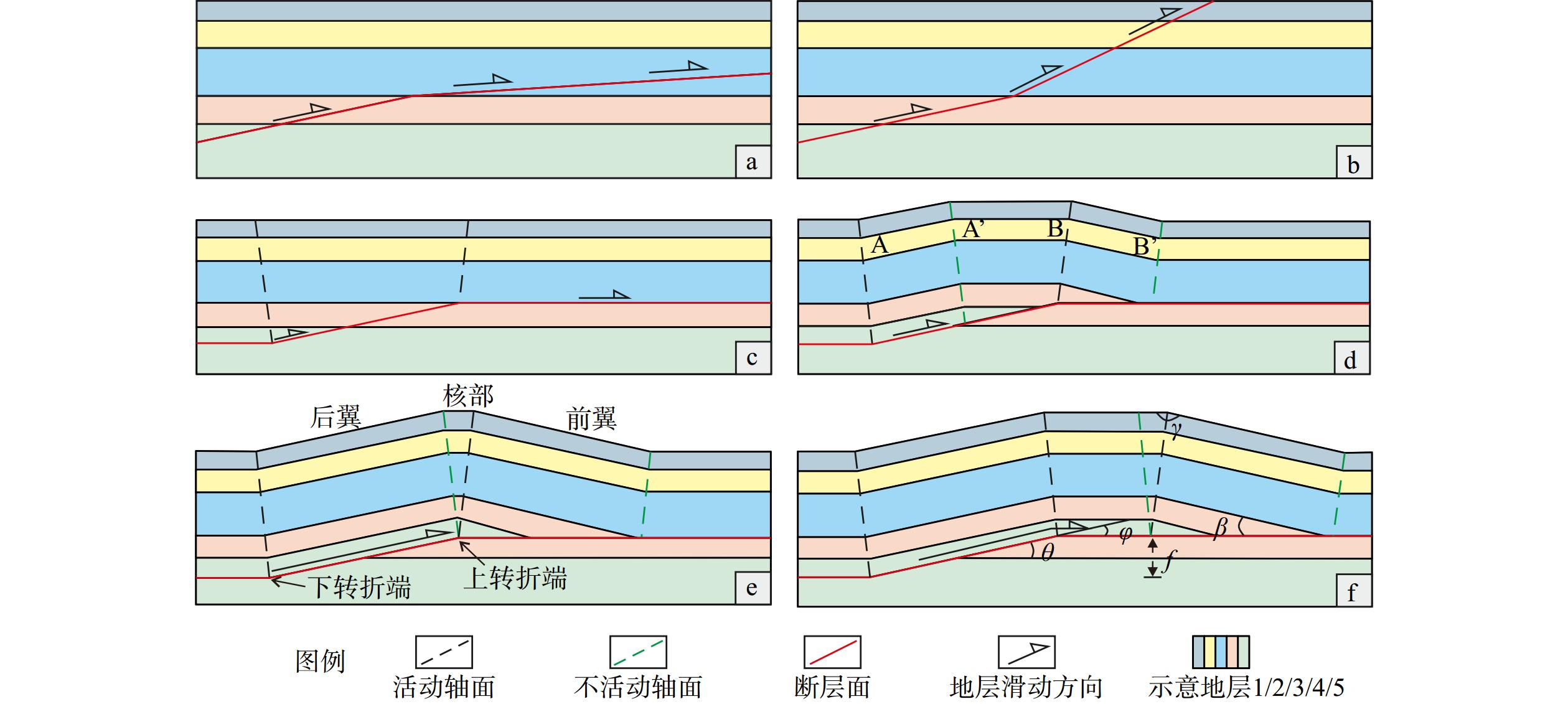
图 1 断层转折褶皱类型及几何学与运动学模型
A、B分别代表初始的活动轴面与不活动轴面;A’与B’分别代表地层沿断层面迁移后的活动轴面与不活动轴面;θ代表断层切层角;φ代表断层转折角;β代表褶皱前翼岩层与断层的地层倾角;γ代表翼间角,轴面与水平面之间的夹角;f代表地层缩短量a—背斜型断层面模型;b—向斜型断层面模型;c—未变形地层中的初始逆冲断层及轴面;d—断层滑动导致上盘岩块沿固定在2个断层弯曲处的活动轴面A和B发生褶皱;e—断层持续滑动导致褶皱处于抬升阶段;f—褶皱持续拓宽阶段
Figure 1. Fault–bend fold types and modeling of geometry and kinematics
(a) Antiform fault–bend model;(b) Synform fault–bend model;(c) Initial thrust fault and axial surfaces in undeformed strata;(d) Fault slip induces folding in the hanging wall along the active axial surfaces A and B, which remain fixed at two fault bends;(e) Continued fault slip leads to the fold uplift stage;(f) Fold widening stage during sustained deformation A and B represent the initial active and inactive axial surfaces, respectively; A' and B' represent the active and inactive axial surfaces after strata displacement along the fault plane; θ is the fault cut-off angle; φ is the fault bend angle; β is the dip angle of the forelimb strata relative to the fault; γ is the angle between the axial surface and the horizontal plane; f denotes the stratal shortening amount.
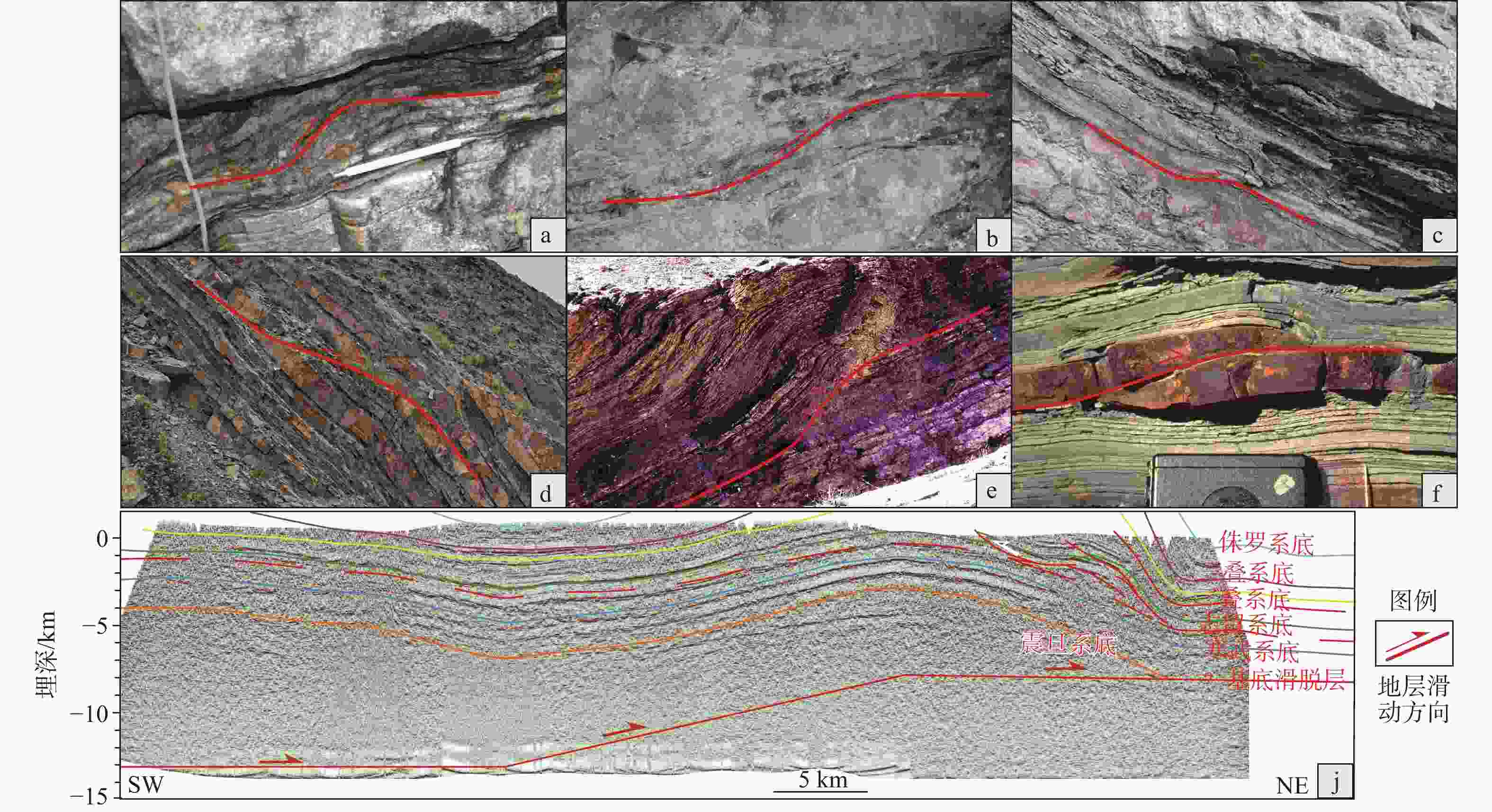
图 2 典型的断层转折褶皱实例
a—川西龙门山石板滩构造带野外露头断层转折褶皱;b—川西龙门山金马–鸭子河构造带野外露头断层转折褶皱;c—鄂尔多斯西缘陇县景福山背斜构造野外露头断层转折褶皱;d—鄂尔多斯西缘乌海苏拜沟桌子山背斜构造野外露头断层转折褶皱;e—斯特拉顿菱铁矿逆冲断层上的断层转折褶皱野外露头(Waldron and Snyder,2020);f—特提斯–喜马拉雅地区断层转折褶皱野外露头(Mukherjee,2020);j—川南长宁地区地震反射剖面地质构造解释(据何登发,2019b修改)
Figure 2. Typical examples of fault–bend folds
(a) Outcrop of a fault–bend fold in the Shibantan Structural Belt, Longmen Shan, western Sichuan; (b) Outcrop of a fault–bend fold in the Jinma–Yazihe Structural Belt, Longmen Shan, western Sichuan; (c) Outcrop of a fault–bend fold in the Jingfushan Anticline, Longxian, western Ordos Margin; (d) Outcrop of a fault–bend fold in the Zuozi Shan Anticline, Subaigou, Wuhai, western Ordos Margin; (e) Outcrop of a fault–bend fold on the Strathcona Siderite Thrust (Waldron and Snyder,2020);(f) Outcrop of a fault–bend fold in the Tethyan–Himalayan Region (Mukherjee, 2020); (j) Structural interpretation of a seismic reflection profile from the Changning Area, southern Sichuan (modified after He, 2019b)
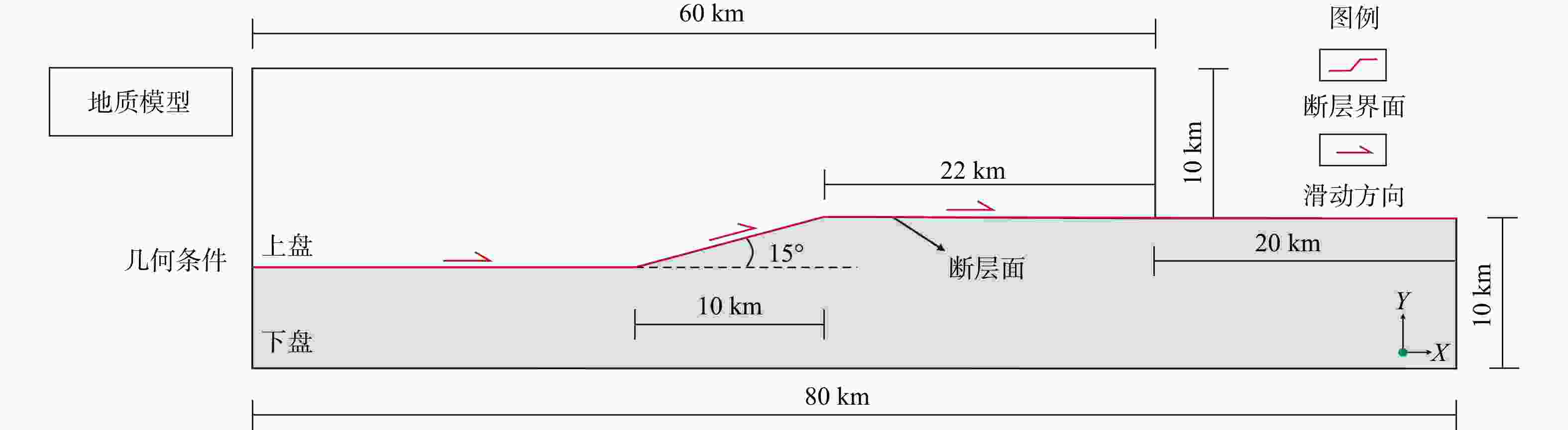
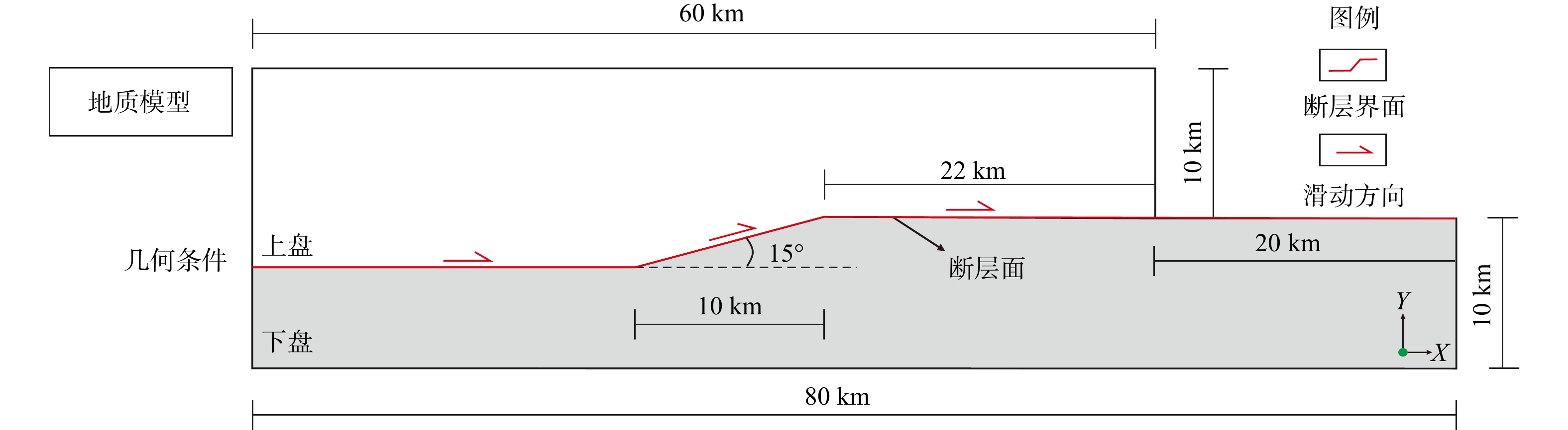
图 3 单层均质断层转折褶皱地质模型
Figure 3. Geological model of a homogeneous single-layer fault–bend fold
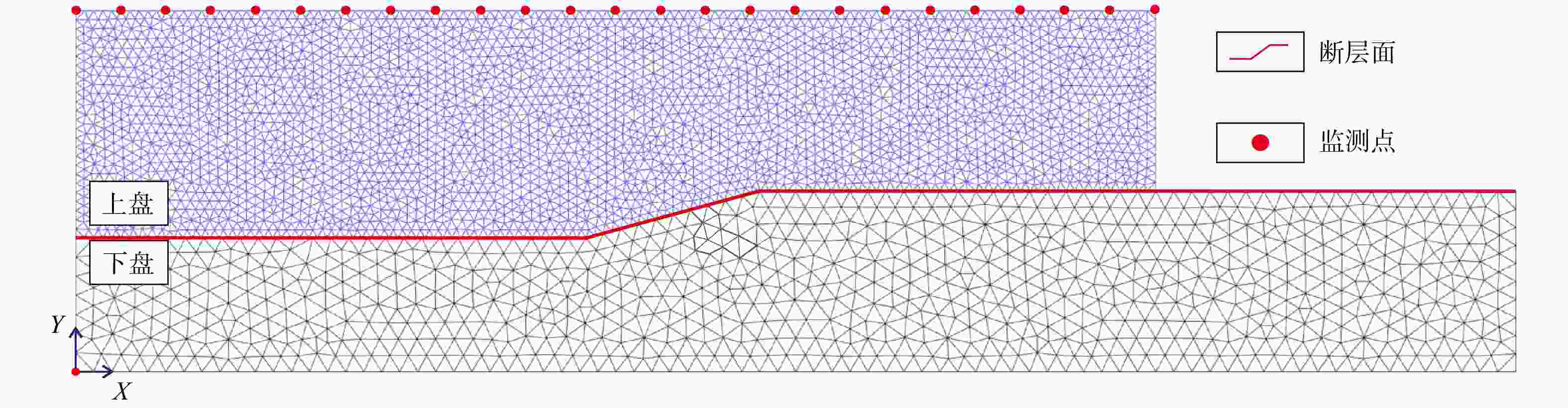
图 4 单层均质断层转折褶皱模型网格划分
Figure 4. Mesh generation for the homogeneous single-layer fault-bend fold model
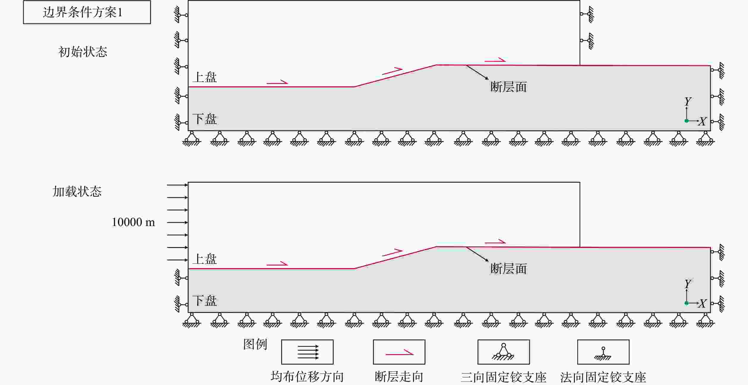
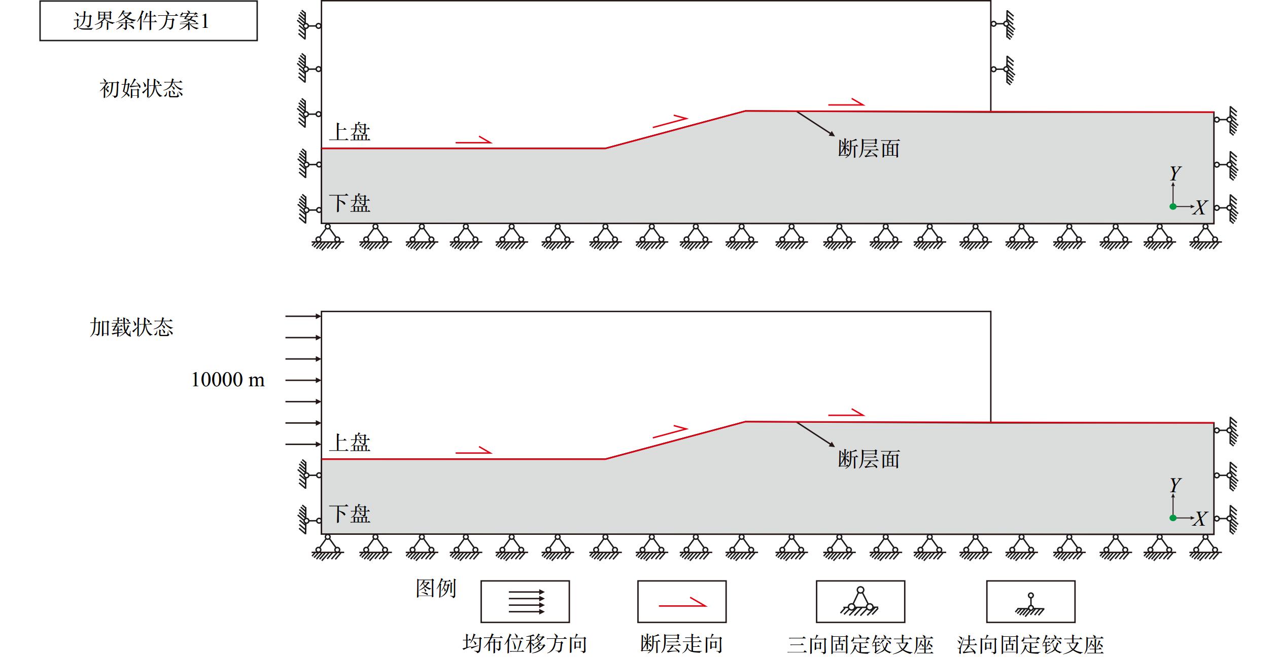
图 5 单层均质断层转折褶皱边界条件方案1
Figure 5. Boundary condition scheme 1 for the homogeneous single-layer fault-bend fold model
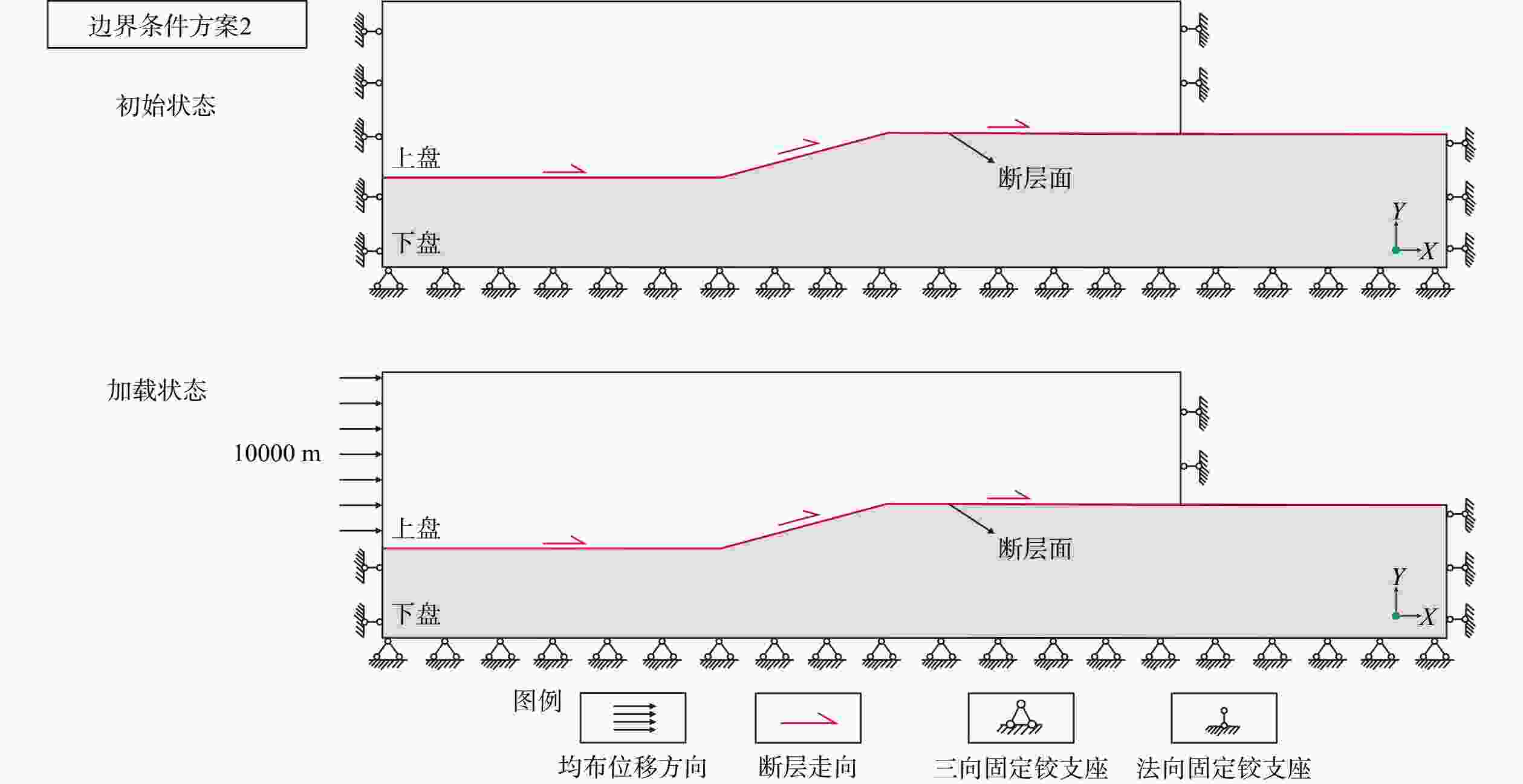
图 6 单层均质断层转折褶皱边界条件方案2
Figure 6. Boundary condition scheme 2 for the homogeneous single-layer fault–bend fold model
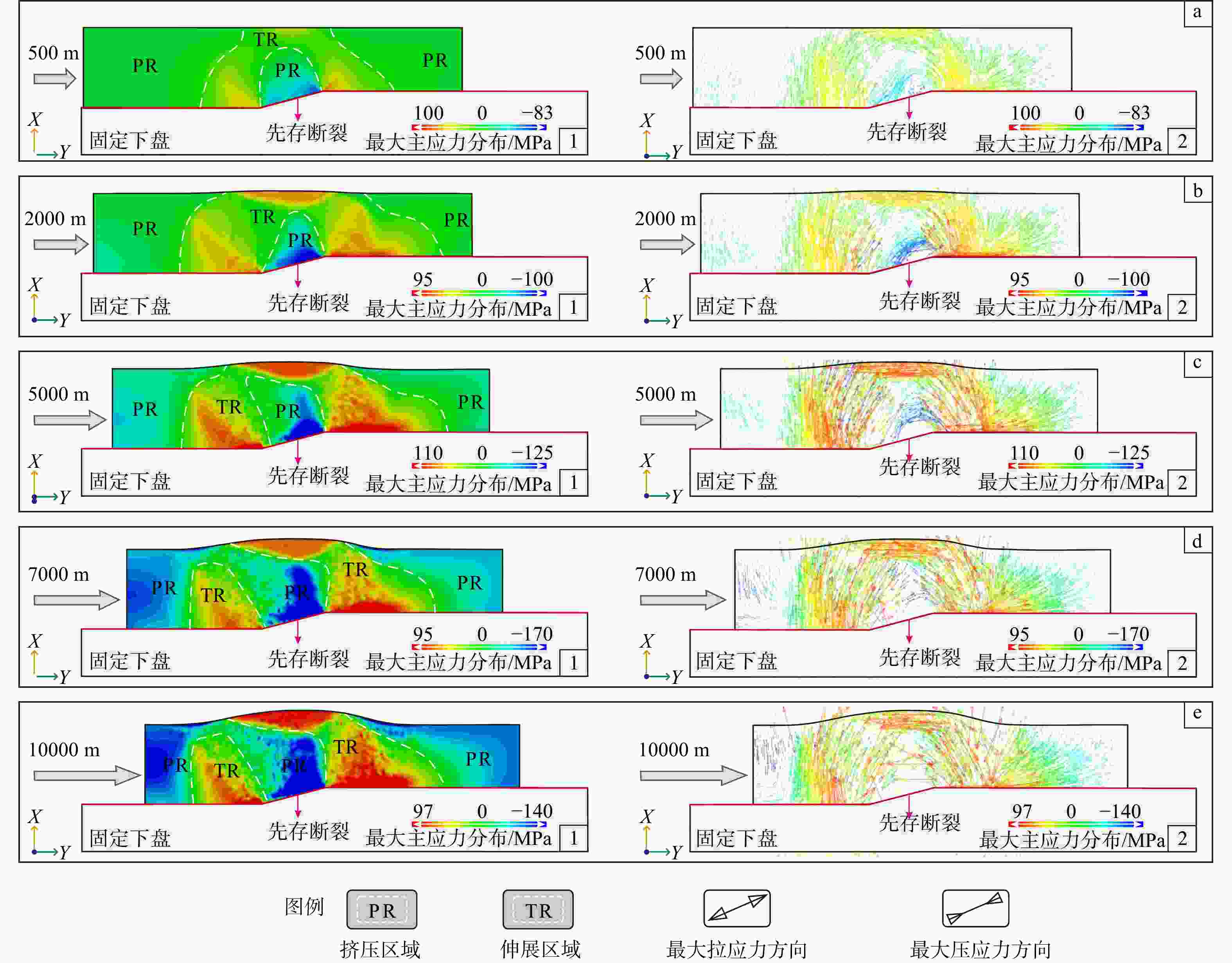
图 7 方案1边界条件下单层均质断层转折褶皱最大主应力大小及方向分布图
a—左侧位移为500 m时最大主应力分布图(a1—大小分布图,a2—方向分布图);b—左侧位移为2000 m时最大主应力分布图(b1—大小分布图,b2—方向分布图);c—左侧位移为5000 m时最大主应力分布图(c1—大小分布图,c2—方向分布图);d—左侧位移为7000m时最大主应力分布图(d1—大小分布图,d2—方向分布图);e—左侧位移为10000 m时最大主应力分布图(e1—大小分布图,e2—方向分布图)
Figure 7. Distribution of the magnitude and orientation of the maximum principal stress in a homogeneous single-layer fault–bend fold under boundary condition scheme 1
(a) Maximum principal stress distribution at a left-side displacement of 500 m (a1–magnitude distribution, a2–orientation distribution); (b) Maximum principal stress distribution at a left-side displacement of 2000 m (b1–magnitude distribution, b2–orientation distribution); (c) Maximum principal stress distribution at a left-side displacement of 5000 m (c1–magnitude distribution, c2–orientation distribution); (d) Maximum principal stress distribution at a left-side displacement of 7000 m (d1–magnitude distribution, d2–orientation distribution); (e) Maximum principal stress distribution at a left-side displacement of 10000 m (e1–magnitude distribution, e2–orientation distribution)
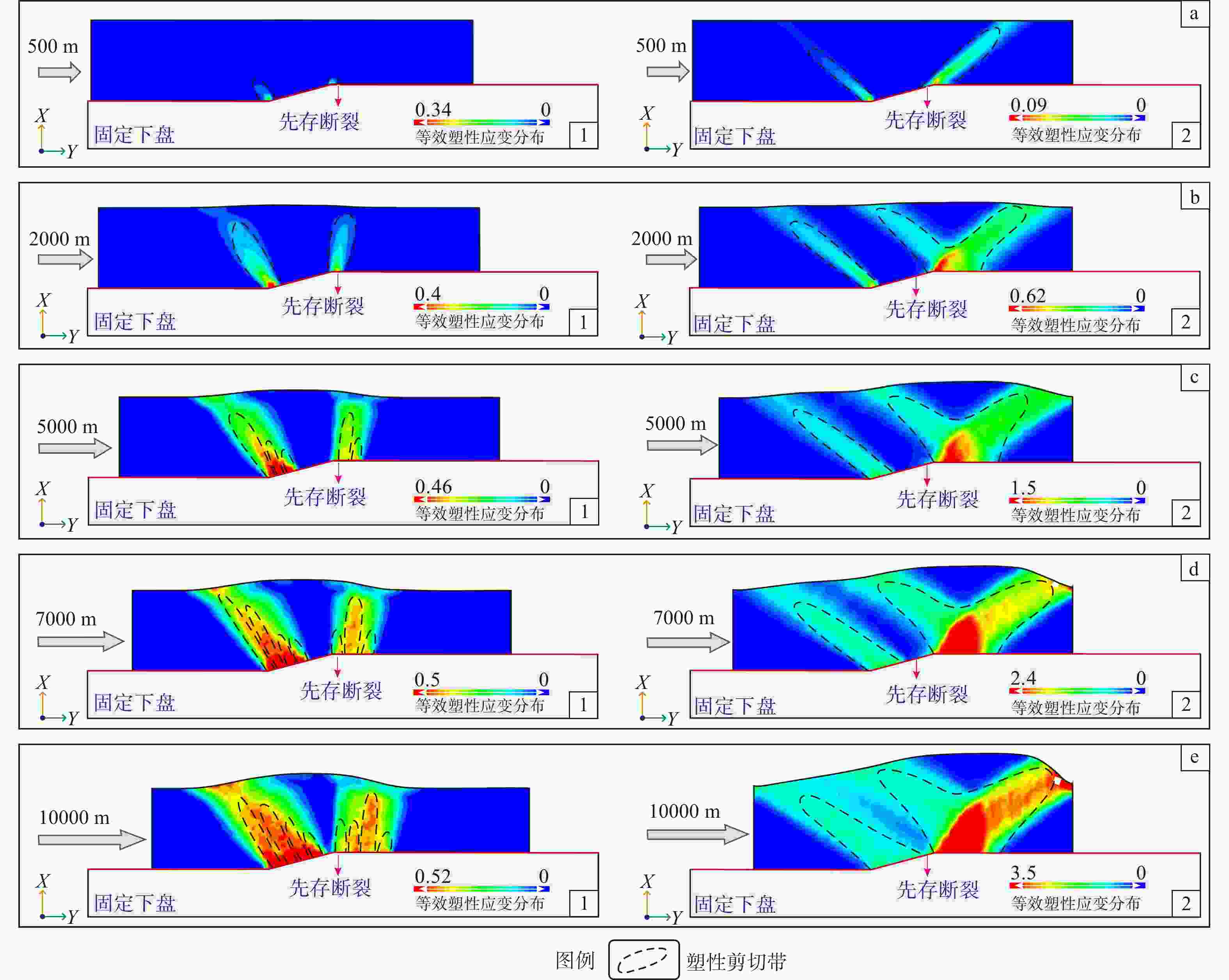
图 8 方案1和2边界条件下单层均质断层转折褶皱等效塑性应变分布图
a—左侧位移为500 m时等效塑性应变分布图(a1—方案1,a2—方案2);b—左侧位移为2000 m时等效塑性应变分布图(b1—方案1,b2—方案2);c—左侧位移为5000 m时等效塑性应变分布图(c1—方案1,c2—方案2);d—左侧位移为7000 m时等效塑性应变分布图(d1—方案1,d2—方案2);e—左侧位移为10000 m时等效塑性应变分布图(e1—方案1,e2—方案2)
Figure 8. Distribution of equivalent plastic strain in a homogeneous single-layer fault–bend fold under boundary conditions schemes 1 and 2
(a)Equivalent plastic strain distribution at a left-side displacement of 500 m (a1–scheme 1, a2–scheme 2); (b)Equivalent plastic strain distribution at a left-side displacement of 2000 m (b1–scheme 1, b2–scheme 2); (c)Equivalent plastic strain distribution at a left-side displacement of 5000 m (c1–scheme 1, c2–scheme 2); (d)Equivalent plastic strain distribution at a left-side displacement of 7000 m (d1–scheme 1, d2–scheme 2); (e)Equivalent plastic strain distribution at a left-side displacement of 10000 m (e1–scheme 1, e2–scheme 2)
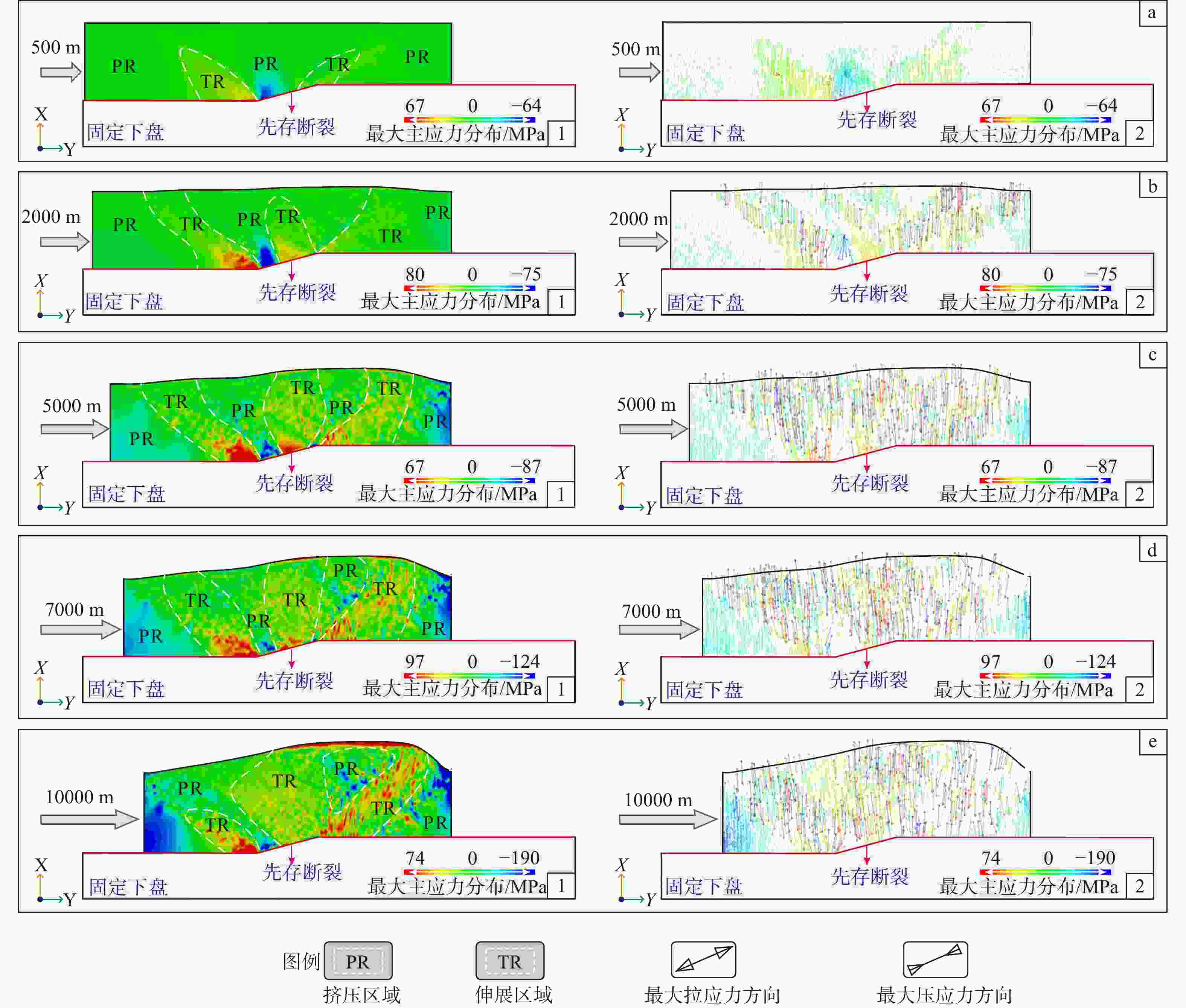
图 9 方案2边界条件下单层均质断层转折褶皱最大主应力大小及方向分布图
a—左侧位移为500 m时最大主应力大小分布图(a1—大小分布图,a2—方向分布图);b—左侧位移为2000 m时最大主应力大小分布图(b1—大小分布图,b2—方向分布图);c—左侧位移为5000 m时最大主应力大小分布图(c1—大小分布图,c2—方向分布图);d—左侧位移为7000 m时最大主应力大小分布图(d1—大小分布图,d2—方向分布图);e—左侧位移为10000 m时最大主应力大小分布图(e1—大小分布图,e2—方向分布图)
Figure 9. Distribution of the magnitude and orientation of the maximum principal stress for a homogeneous single-layer fault–bend fold under boundary condition scheme 2
(a) Maximum principal stress distribution at a left-side displacement of 500 m (a1–magnitude distribution, a2–orientation distribution); (b) Maximum principal stress distribution at a left-side displacement of 2000 m (b1–magnitude distribution, b2–orientation distribution); (c) Maximum principal stress distribution at a left-side displacement of 5000 m (c1–magnitude distribution, c2–orientation distribution); (d) Maximum principal stress distribution at a left-side displacement of 7000 m (d1–magnitude distribution, d2–orientation distribution); (e) Maximum principal stress distribution at a left-side displacement of 10000 m (e1–magnitude distribution, e2–orientation distribution)
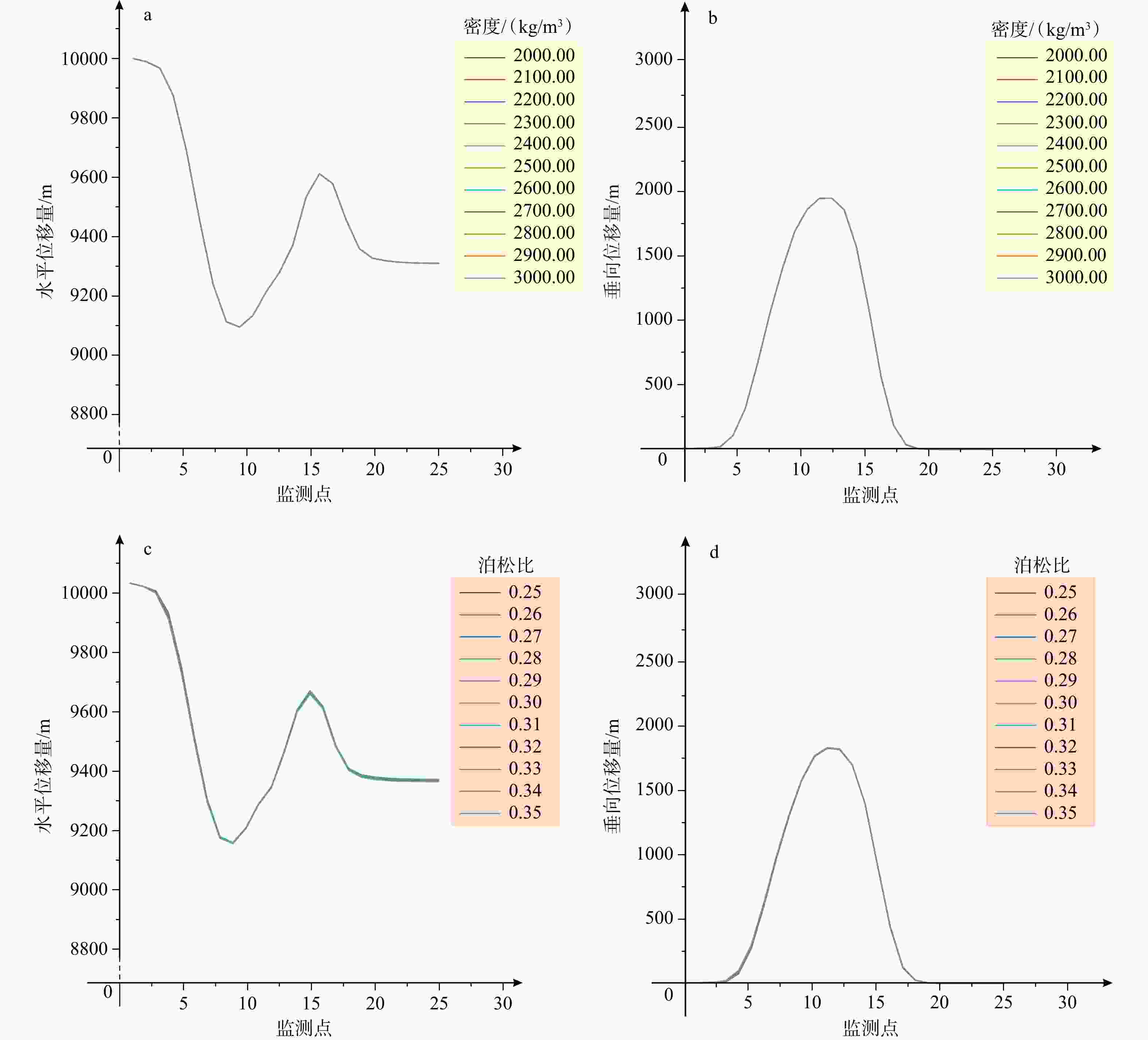
图 10 密度与泊松比参数单因素下多组实验褶皱顶部位移数据曲线图
a—密度参数下褶皱顶部水平位移;b—密度参数下褶皱顶部垂向位移;c—泊松比参数下褶皱顶部水平位移;d—泊松比参数下褶皱顶部垂向位移
Figure 10. Displacement data curves at the fold crest from multiple sets of experiments under the single-factor condition of density and Poisson's ratio parameters
(a) Horizontal displacement at the fold crest under the density parameter; (b) Vertical displacement at the fold crest under the density parameter; (c) Horizontal displacement at the fold crest under the Poisson's ratio parameter; (d) Vertical displacement at the fold crest under the Poisson's ratio parameter
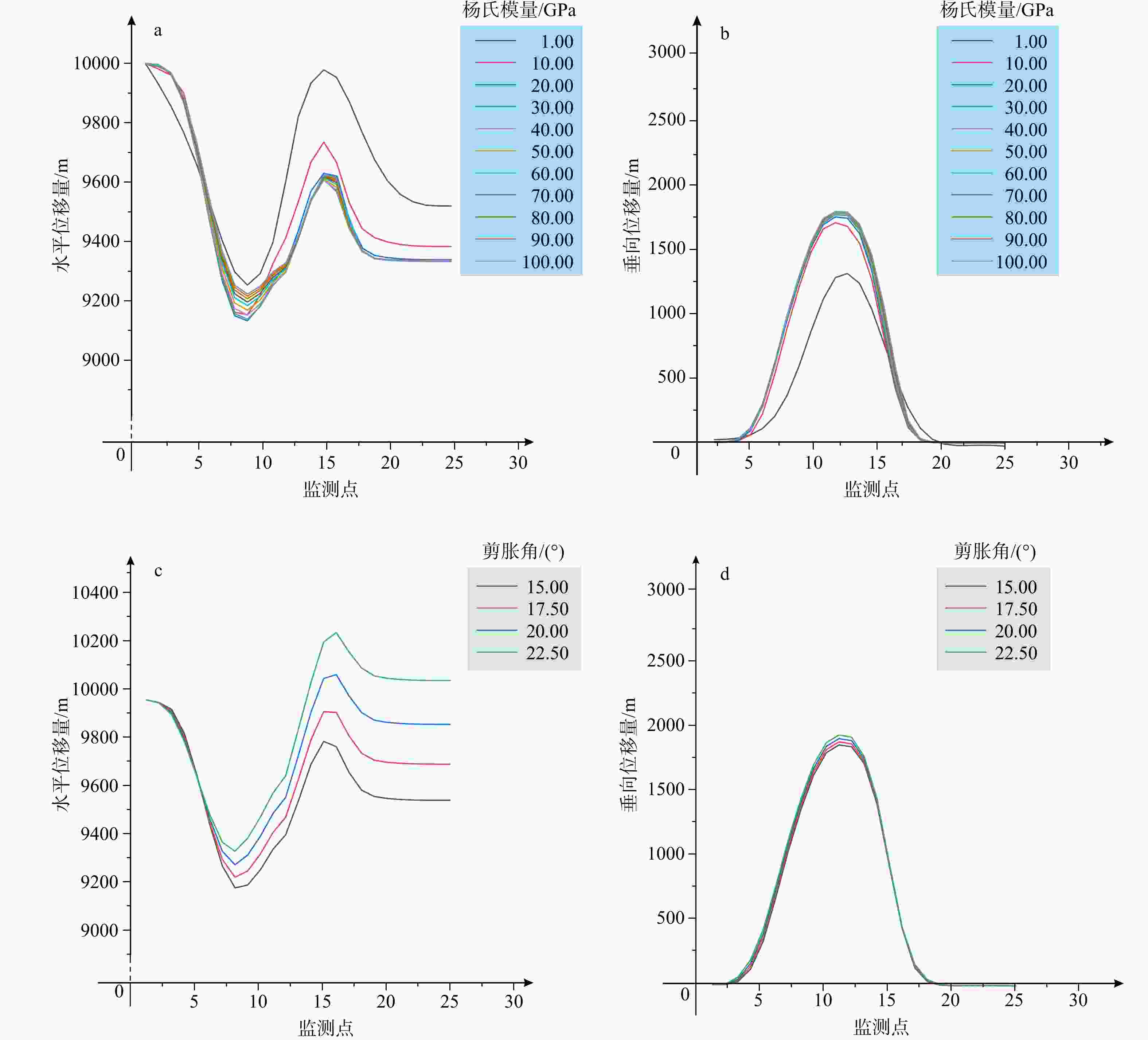
图 11 杨氏模量与剪胀角参数单因素下多组实验褶皱顶部位移数据曲线图
a—杨氏模量参数下褶皱顶部水平位移;b—杨氏模量参数下褶皱顶部垂向位移;c—剪胀角参数下褶皱顶部水平位移;d—剪胀角参数下褶皱顶部垂向位移
Figure 11. Displacement data curves at the fold crest from multiple sets of experiments under the single-factor condition of Young's modulus and dilation angle parameters
(a) Horizontal displacement at the fold crest under the Young's modulus parameter; (b) Vertical displacement at the fold crest under the Young's modulus parameter; (c) Horizontal displacement at the fold crest under the dilation angle parameter; (d) Vertical displacement at the fold crest under the dilation angle parameter
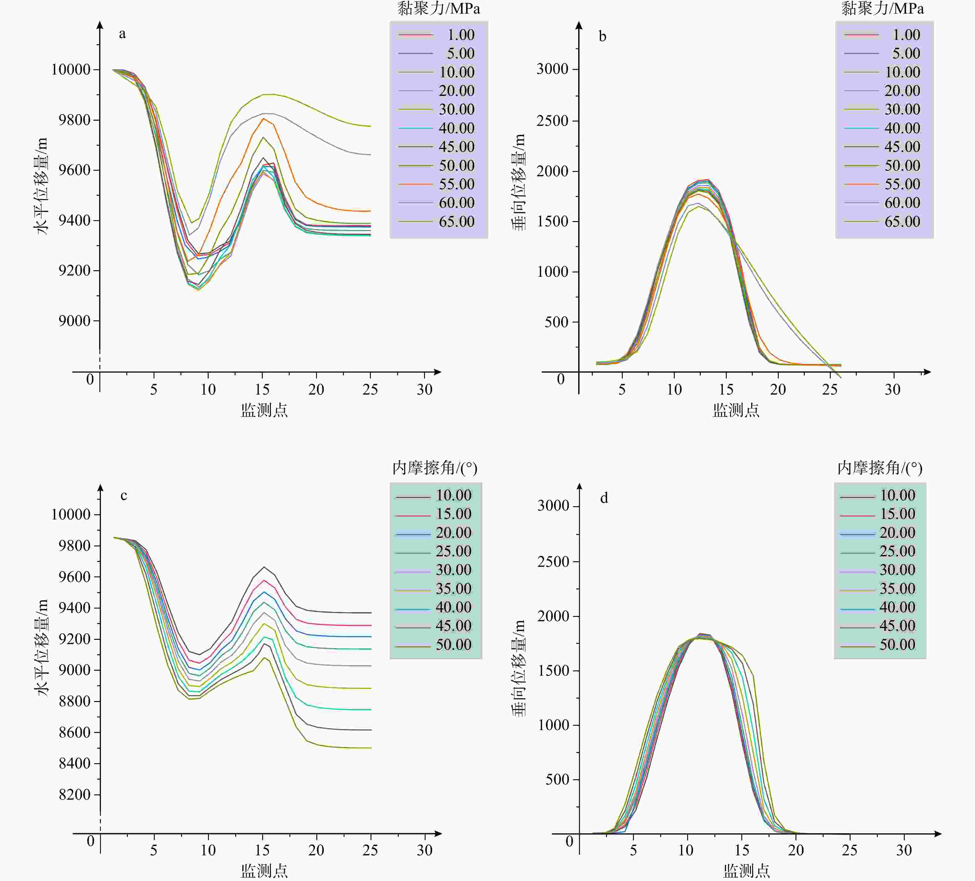
图 12 黏聚力与内摩擦角参数单因素下多组实验褶皱顶部位移数据曲线图
a—黏聚力参数下褶皱顶部水平位移;b—黏聚力参数下褶皱顶部垂向位移;c—内摩擦角参数下褶皱顶部水平位移;d—内摩擦角参数下褶皱顶部垂向位移
Figure 12. Displacement data curves at the fold crest from multiple sets of experiments under the single-factor condition of cohesion and internal friction angle parameters
(a) Horizontal displacement at the fold crest under the cohesion parameter; (b) Vertical displacement at the fold crest under the cohesion parameter; (c) Horizontal displacement at the fold crest under the internal friction angle parameter; (d) Vertical displacement at the fold crest under the internal friction angle parameter
表 1 断层转折褶皱模型参数设置表
Table 1. Parameters for the fault–bend fold model
密度/(kg/m3) 杨氏模量/GPa 泊松比 内摩擦角/(°) 黏聚力/MPa 剪胀角/(°) 上盘 2500 20 0.34 21.38 34.31 42.78 下盘 2700 55 0.28 40 20 50  下载: 导出CSV
表 2 断层转折褶皱模型上盘单一参数变量取值表
Table 2. Values of single-parameter variables for the hanging wall in the fault–bend fold model
密度/(kg/m3) 杨氏模量/GPa 泊松比 内摩擦角/(°) 黏聚力/MPa 剪胀角/(°) 2000.00 1.00 0.25 15.00 1.00 15.00 2100.00 10.00 0.26 20.00 5.00 17.50 2200.00 20.00 0.27 25.00 10.00 20.00 2300.00 30.00 0.28 30.00 20.00 22.50 2400.00 40.00 0.29 35.00 30.00 25.00 2500.00 50.00 0.30 40.00 40.00 27.50 2600.00 60.00 0.31 45.00 45.00 30.00 2700.00 70.00 0.32 50.00 50.00 32.50 2800.00 80.00 0.33 55.00 60.00 35.00 2900.00 90.00 0.34 60.00 70.00 37.50 3000.00 100.00 0.35 65.00 80.00 40.00
下载: 导出CSV
表 3 不同弹塑性参数单因素下多组实验几何参数结果表
Table 3. Results of geometric parameters from multiple single-factor experiments with different elastoplastic parameters
参数名称 几何参数取值 半波长W 倾角$ \theta $ 后翼$ {\theta }_{2} $ 前翼$ {\theta }_{1} $ 差值(Δ$ \theta $=$ {\theta }_{1} $−$ {\theta }_{2} $) 杨氏模量 1 GPa 38.44 km 8.50° 8.79° 0.21° 10 GPa 33.94 km 11.19° 15.27° 4.08° 20 GPa 33.88 km 12.44° 15.47° 3.03° 30 GPa 34.08 km 12.92° 16.37° 3.45° 40 GPa 34.33 km 11.39° 14.25° 2.89° 50 GPa 34.41 km 12.28° 15.25° 2.97° 60 GPa 34.61 km 10.67° 14.95° 4.28° 70 GPa 34.62 km 11.12 ° 14.43° 3.31° 80 GPa 34.82 km 11.51° 14.07° 2.56° 90 GPa 34.81 km 11.96° 14.64 2.68° 100 GPa 34.84 km 11.42° 16.59° 5.17° 剪切角 15.0° 35.85 km 11.06 ° 14.06° 3.00° 17.5° 36.77 km 11.09° 14.33° 3.24° 20.0° 37.47 km 12.01° 15.51° 3.50° 22.5° 38.51 km 12.09° 15.97° 3.85° 黏聚力 1 MPa 35.86 km 12.88° 14.62° 1.74° 5 MPa 35.97 km 12.25° 14.38° 1.83° 10 MPa 34.71 km 12.86° 14.64° 1.78° 20 MPa 34.65 km 11.66° 15.19° 3.53° 30 MPa 34.36 km 11.49° 15.00° 3.51° 40 MPa 34.08 km 11.03° 14.87° 3.84° 45 MPa 33.89 km 12.24° 14.99° 2.75° 50 MPa 34.35 km 12.09° 13.92° 1.83° 55 MPa 35.25 km 12.49° 14.10° 1.61° 60 MPa° 46.86 km 12.15° 5.29° −6.86° 70 MPa 47.97 km 10.62° 5.17° −5.45° 内摩擦角 10° 33.76 km 9.46° 10.68° 1.22° 15° 34.04 km 9.16° 10.76° 1.6° 20° 34.09 km 9.40° 11.39° 1.99° 25° 34.16 km 9.88° 11.40° 1.52° 30° 34.93 km 9.32 ° 11.58° 2.26° 35° 36.42 km 10.01° 12.75° 2.74° 40° 37.79 km 11.57° 18.84° 7.27° 45° 38.84 km 11.32° 24.39° 13.07° 50° 39.68 km 11.87° 25.54° 13.67° 注:前翼是指褶皱运动方向
下载: 导出CSV
-
[1] BO D L, 2014. Elastic-plastic analysis of gravity stress of spherical shell based on the Mohr-coulomb yield criterion[J]. Value Engineering, 33(32): 316-318. (in Chinese with English abstract) [2] BONINI M, SOKOUTIS D, MULUGETA G, et al., 2000. Modelling hanging wall accommodation above rigid thrust ramps[J]. Journal of Structural Geology, 22(8): 1165-1179. doi: 10.1016/S0191-8141(00)00033-X [3] BRANDES C, TANNER D C, 2014. Fault-related folding: a review of kinematic models and their application[J]. Earth-Science Reviews, 138: 352-370. doi: 10.1016/j.earscirev.2014.06.008 [4] CAI Z Z, HUANG S Y, WANG Y R, 2011. A simple geometry method for analyzing angle relationship of fault-bend fold model[J]. Acta Scientiarum Naturalium Universitatis Pekinensis, 47(4): 684-688. (in Chinese with English abstract) [5] CHEN J, LU H F, WANG S L, 2002. Testing of cut-off angles of the Kuqa fault-related folds[J]. Geological Review, 48(1): 74-79. (in Chinese with English abstract) [6] CHEN J, LU H F, YU J Z, et al., 2005. Geometric models of fault-related folds and their application[J]. Acta Geoscientica Sinica, 26(1): 89-92. (in Chinese with English abstract) [7] CHEN J J, HE D F, SUN F Y, et al., 2018. Geometry and kinematics of Wensu swell in North Tarim uplift[J]. Xinjiang Petroleum Geology, 39(3): 318-325. (in Chinese with English abstract) [8] CHESTER F M, 1995. A rheologic model for wet crust applied to strike‐slip faults[J]. Journal of Geophysical Research: Solid Earth, 100(B7): 13033-13044. doi: 10.1029/95JB00313 [9] CONNORS C D, HUGHES A N, BALL S M, 2021. Forward kinematic modeling of fault-bend folding[J]. Journal of Structural Geology, 143: 104252. doi: 10.1016/j.jsg.2020.104252 [10] CRISTALLINI E O, GIAMBIAGI L, ALLMENDINGER R W, 2004. True three-dimensional trishear: a kinematic model for strike-slip and oblique-slip deformation[J]. Geological Society of America Bulletin, 116(7-8): 938-952. [11] DAHLSTROM C D A, 1969. Balanced cross sections[J]. Canadian Journal of Earth Sciences, 6(4): 743-757. doi: 10.1139/e69-069 [12] ERICKSON S G, STRAYER L M, SUPPE J, 2004. Numerical modeling of hinge-zone migration in fault-bend folds[M]//MCCLAY K R. Thrust tectonics and hydrocarbon systems. Tulsa: American Association of Petroleum Geologists: 438-452. [13] FORD M, WILLIAMS E A, ARTONI A, et al., 1997. Progressive evolution of a fault-related fold pair from growth strata geometries, Sant Llorenç de Morunys, SE Pyrenees[J]. Journal of Structural Geology, 19(3-4): 413-441. doi: 10.1016/S0191-8141(96)00116-2 [14] HE D F, SUPPE J, JIA C Z, 2005. New advances in theory and application of fault-related folding[J]. Earth Science Frontiers, 12(4): 353-364. (in Chinese with English abstract) [15] HE D F, SUPPE J, 2007. Theory and application of tri-shear fault propagation folding[J]. Earth Science Frontiers, 14(4): 66-73. (in Chinese with English abstract) [16] HE D F, SHAO D B, KAI B Z, et al., 2019a. Structural style and trap distribution in Majiatan area on the western margin of ordos basin[J]. Acta Geoscientica Sinica, 40(1): 219-235. (in Chinese with English abstract) [17] HE D F, LU R Q, HUANG H Y, et al., 2019b. Tectonic and geological background of the earthquake hazards in Changning shale gas development zone, Sichuan Basin, SW China[J]. Petroleum Exploration and Development, 46(5): 993-1006. (in Chinese with English abstract) [18] HUANG D F, JIANG M L, SHAO M J, et al., 2020. Structural style and evolution of northern piedmont belt in Turpan-Hami basin[J]. Xinjiang Petroleum Geology, 41(6): 651-657. (in Chinese with English abstract) [19] JAMISON W R, 1987. Geometric analysis of fold development in overthrust terranes[J]. Journal of Structural Geology, 9(2): 207-219. doi: 10.1016/0191-8141(87)90026-5 [20] JU W, HOU G T, ZHANG B, 2014. Insights into the damage zones in fault-bend folds from geomechanical models and field data[J]. Tectonophysics, 610: 182-194. doi: 10.1016/j.tecto.2013.11.022 [21] KHALIFEH-SOLTANI A, ALAVI S A, GHASSEMI M R, et al., 2023. Stress and strain evolution in fault-related folds: insights from 2D geomechanical modelling[J]. Frontiers in Earth Science, 11: 1249446. doi: 10.3389/feart.2023.1249446 [22] KING HUBBERT M, RUBEY W W, 1959. Role of fluid pressure in mechanics of overthrust faulting: I. Mechanics of fluid-filled porous solids and its application to overthrust faulting[J]. GSA Bulletin, 70(2): 115-166. doi: 10.1130/0016-7606(1959)70[115:ROFPIM]2.0.CO;2 [23] LI B L, SUN Y, ZHU W B, et al., 2001. Study on the layer-slip parameter systems in the eastern Sichuan[J]. Journal of Southwest Petroleum University, 23(1): 29-33. (in Chinese with English abstract) [24] LI Y, HOU G T, HARI K R, et al. , 2018. The model of fracture development in the faulted folds: the role of folding and faulting[J]. Marine and Petroleum Geology, 89(Pt 2): 243-251. [25] LIU C L, ZHANG Y Q, ZHANG Y, et al., 2018. Analysis of regional structural cross section of the North and Central Tarim Basin and new insights into paleo-uplift origin[J]. Oil & Gas Geology, 39(5): 1001-1010. (in Chinese with English abstract) [26] LU H F, JIA D, CHEN C M, et al., 1999. Nature and timing of the Kuqa Cenozoic structures[J]. Earth Science Frontiers, 6(4): 215-221. (in Chinese with English abstract) [27] MA J, HE D F, ZHANG W K, et al., 2024. Numerical simulation of present-day stress field on the top surface of Ordovician Wufeng Formation shale in the Shilongxia anticline area, Southeast Sichuan, China[J]. Chinese Journal of Geology, 59(3): 792-803. (in Chinese with English abstract) [28] MA L C, JIANG W, SHI H, et al,2024. The Relationship Between Cenozoic Superimposed Folds and Hydrocarbon Migration in the Gahainanshan Area, Eastern Qaidam Basin, China[J]. Geoscience, 38(05): 1209-1220. (in Chinese with English abstract) [29] MUKHERJEE S, 2020. Atlas of structural geology[M]. 2nd ed. Amsterdam: Elsevier: 1-2. [30] PLOTEK B, GUZMÁN C , CRISTALLINI E, et al. , 2021. Analysis of fault bend folding kinematic models and comparison with an analog experiment[J]. Journal of Structural Geology, 146: 104316. [31] POBLET J, 2020. Cartographic pattern of terminations of simple, parallel fault-bend folds, fault-propagation folds and detachment folds[J]. Journal of Structural Geology, 138: 104135. doi: 10.1016/j.jsg.2020.104135 [32] RICH J L, 1934. Mechanics of low-angle overthrust faulting as illustrated by Cumberland thrust block, Virginia, Kentucky, and Tennessee[J]. AAPG Bulletin, 18(12): 1584-1596. [33] SCHMALHOLZ S M, PODLADCHIKOV Y Y, BURG J P, 2002. Control of folding by gravity and matrix thickness: implications for large-scale folding[J]. Journal of Geophysical Research: Solid Earth, 107(B1): ETG 1-1-ETG 1-16. [34] SHAO Y, CHEN W, ZHANG B Y, 2005. Application of the geometry of fault-related folding to the southern Junggar Basin[J]. Journal of Earth Sciences and Environment, 27(1): 26-29. (in Chinese with English abstract) [35] SHI J, HE D F, BAO H P, et al., 2024. Tectonic analysis of the eastern boundary of Ordos Basin: a case study of northern region of Shilou area[J]. Journal of Palaeogeography, 26(1): 150-164. (in Chinese with English abstract) [36] SUN C W, LING S X, ZHAO S Y, et al., 2022. Quantitative evaluation of coseismic deformations induced by seismogenic faulting in mining exploration area during the 2018 Xingwen and 2019 Changning earthquakes, Sichuan, China[J]. Frontiers in Earth Science, 10: 880692. doi: 10.3389/feart.2022.880692 [37] SUPPE J, 1983. Geometry and kinematics of fault-bend folding[J]. American Journal of Science, 283(7): 684-721. doi: 10.2475/ajs.283.7.684 [38] TIAN M N, SUN W, MENG X W, et al., 2016. Research of fault-related folds characteristics in Chishui area, Southeast Sichuan basin[J]. Journal of Guilin University of Technology, 36(4): 644-651. (in Chinese with English abstract) [39] TONG H M, ZHANG H X, HOU Q L, et al., 2024. Generalized fracturing activation criteria[J]. Journal of Geomechanics, 30(1): 3-14. (in Chinese with English abstract) [40] WALDRON J, SNYDER M, 2020. Geological structures: a practical introduction[M]. Edmonton: University of Alberta: 143. [41] WANG B, WANG W, ZHU L C, et al., 2019. Fault-related fold and its application to Madong fold and thrust belt[J]. Geological Journal of China Universities, 25(2): 268-275. (in Chinese with English abstract) [42] WANG H C, ZHAO W H, SUN D S, et al., 2012. Mohr-Coulomb yield criterion in rock plastic mechanics[J]. Chinese Journal of Geophysics, 55(12): 4231-4238. (in Chinese with English abstract) [43] WANG K, JIA D, LUO L, et al., 2014. Magnetic fabric and finite strain analysis of the Qiongxi fault-bend fold in the southern Longmen mountain[J]. Geological Bulletin of China, 33(5): 629-640. (in Chinese with English abstract) [44] WANG L, WU Z Y, YIN H W, et al., 2021. Compressional salt structures of salt-bearing sedimentary basins and its significance to hydrocarbon accumulation[J]. Bulletin of Geological Science and Technology, 40(5): 136-150. (in Chinese with English abstract) [45] WANG M M, 2013. Active fault-related folding in the South Longmen Shan fold-and-thrust belt and earthquake hazard risk analysis in the Sichuan basin[D]. Nanjing: Nanjing University. (in Chinese with English abstract) [46] WANG R, YIN Y Q, 1981. On the elasto-plastic constitutive equation of engineering rock-like materials[J]. Chinese Journal of Theoretical and Applied Mechanics, 17(4): 317-325. (in Chinese with English abstract) [47] WANG S J, YAN D P, ZHOU Z C, et al, 2025. Tectonic Characteristics and Evolution of the Qiyueshan Fault in the Xuefengshan Foreland Fold-and-Thrust Belt: Insights from Discrete Element Numerical Simulations[J]. Geoscience, 39(1): 18-30. (in Chinese with English abstract) [48] WANG X C, 2003. Finite element method[M]. Beijing: Tsinghua University Press. (in Chinese) [49] WANG Y J, WEI D T, PAN J G, et al. , 2012. A quantitative modeling method for fault-related fold and its application[J]. Lithologic Reservoirs, 24(4): 99-103, 128. (in Chinese with English abstract) [50] WU Y Q, JIANG Z S, LIANG H B, et al., 2018. Deformation response of seismogenic faults to the Wenchuan MS 8.0 earthquake: a case study for the southern segment of the Longmenshan fault zone[J]. Remote Sensing, 10(6): 894. doi: 10.3390/rs10060894 [51] YANG J H, 2021. Characteristics and genetic mechanism of tectonic deformation in basin-mountain transitional zone: a case study of Sangmuchang Anticline in southeastern Sichuan Basin[J]. Oil & Gas Geology, 42(2): 416-429. (in Chinese with English abstract) [52] YANG J H, HE D F, ZHANG W K, et al., 2022. Three-dimensional geometry and kinematics of the Changning anticline in the southern Sichuan Basin[J]. Acta Geologica Sinica-English Edition, 96(4): 1432-1450. doi: 10.1111/1755-6724.14981 [53] YANG S H, LUO L, MA S J, et al., 2024. Structural deformation and shale gas preservation conditions in the Changning area of the southern Sichuan Basin[J]. Geoscience, 38(6): 1458-1472. (in Chinese with English abstract) [54] YANG X Q, CHEN W, YU Y L, et al., 2020. Finite element simulation of plastic strain distribution characteristics and structural significance of fault turning fold[J]. Chemical Engineering Design Communications, 46(1): 232-233. (in Chinese with English abstract) [55] YIN L, LUO G, 2018. Crustal deformation across the Longmen Shan fault zone from finite element simulation of seismic cycles[J]. Chinese Journal of Geophysics, 61(4): 1238-1257. (in Chinese with English abstract) [56] YUAN J, ZHU S B, 2014. FEM simulation of the dynamic processes of fault spontaneous rupture[J]. Chinese Journal of Geophysics, 57(1): 138-156. (in Chinese with English abstract) [57] ZHANG B L, ZHU G, JIANG D Z, et al., 2009. Numerical modeling and formation mechanism of the eastern Sichuan jura-type folds[J]. Geological Review, 55(5): 701-711. (in Chinese with English abstract) [58] ZHANG R Q, ZHAN X Y, 1990. Nonlinear finite element analysis[M]. Chongqing: Chongqing University Press. (in Chinese) [59] ZHANG Y K, SUPPE J, JIA D, et al., 2005. Geometric forward modeling of generalized “fault-bend folding”[J]. Geological Journal of China Universities, 11(4): 608-616. (in Chinese with English abstract) [60] ZHUANG Z, YOU X C, LIAO J H, et al. , 2009. Finite element analysis and application based on ABAQUS[M]. Beijing: Tsinghua University Press. (in Chinese) [61] ZU K W, ZENG L B, ZHAO X Y, et al., 2014. Discussion on development models of the shearing fractures in fault bend folds[J]. Journal of Geomechanics, 20(1): 16-24. (in Chinese with English abstract) [62] 柏东良, 2014. 基于摩尔库伦准则的球壳自重应力弹塑性分析[J]. 价值工程, 33(32): 316-318. doi: 10.3969/j.issn.1006-4311.2014.32.173 [63] 蔡振忠, 黄少英, 王月然, 2011. 断层转折褶皱角度参数关系的一种几何学分析方法[J]. 北京大学学报(自然科学版), 47(4): 684-688. doi: 10.13209/j.0479-8023.2011.096 [64] 陈槚俊, 何登发, 孙方源, 等, 2018. 温宿凸起构造几何学与运动学特征[J]. 新疆石油地质, 39(3): 318-325. doi: 10.7657/XJPG20180309 [65] 陈剑, 卢华复, 王胜利, 2002. 库车断层相关褶皱的切角检验[J]. 地质论评, 48(1): 74-79. doi: 10.3321/j.issn:0371-5736.2002.01.012 [66] 陈剑, 卢华复, 于景宗, 等, 2005. 断层相关褶皱的几何学模型及其应用[J]. 地球学报, 26(1): 89-92. doi: 10.3321/j.issn:1006-3021.2005.01.014 [67] 何登发, SUPPE J, 贾承造, 2005. 断层相关褶皱理论与应用研究新进展[J]. 地学前缘, 12(4): 353-364. [68] 何登发, SUPPE J, 2007. 三角剪切断层传播褶皱作用理论与应用[J]. 地学前缘, 14(4): 66-73. [69] 何登发, 邵东波, 开百泽, 等, 2019a. 鄂尔多斯盆地西缘马家滩地区的构造样式与圈闭分布规律[J]. 地球学报, 40(1): 219-235. doi: 10.3975/cagsb.2018.100801 [70] 何登发, 鲁人齐, 黄涵宇, 等, 2019b. 长宁页岩气开发区地震的构造地质背景[J]. 石油勘探与开发, 46(5): 993-1006. doi: 10.11698/PED.2019.05.19 [71] 黄蝶芳, 姜萌蕾, 邵满军, 等, 2020. 吐哈盆地北部山前带构造样式及演化特征[J]. 新疆石油地质, 41(6): 651-657. doi: 10.7657/XJPG20200603 [72] 李本亮, 孙岩, 朱文斌, 等, 2001. 川东地区层滑参数系统研究[J]. 西南石油学院学报, 23(1): 29-33. doi: 10.3863/j.issn.1674-5086.2001.01.008 [73] 刘长磊, 张艺琼, 张永, 等, 2018. 塔北-塔中区域构造地质大剖面解析及古隆起成因新解[J]. 石油与天然气地质, 39(5): 1001-1010. doi: 10.11743/ogg20180514 [74] 卢华复, 贾东, 陈楚铭, 等, 1999. 库车新生代构造性质和变形时间[J]. 地学前缘, 6(4): 215-222. doi: 10.3321/j.issn:1005-2321.1999.04.003 [75] 马佳, 何登发, 张伟康, 等, 2024. 川东南石龙峡背斜区奥陶系五峰组页岩顶面现今应力场数值模拟研究[J]. 地质科学, 59(3): 792-803. doi: 10.12017/dzkx.2024.057 [76] 马立成, 江万, 施辉, 等, 2024. 柴达木盆地东部尕海南山地区新生代叠加褶皱与油气运移[J]. 现代地质, 38(05): 1209-1220. [77] 邵雨, 陈伟, 张伯友, 2005. 断层相关褶皱理论在准噶尔盆地南缘山前带构造研究的应用[J]. 地球科学与环境学报, 27(1): 26-29. doi: 10.3969/j.issn.1672-6561.2005.01.005 [78] 石婧, 何登发, 包洪平, 等, 2024. 鄂尔多斯盆地东部边界的构造学分析: 以石楼北地区为例[J]. 古地理学报, 26(1): 150-164. doi: 10.7605/gdlxb.2024.01.003 [79] 田梦娜, 孙玮, 孟宪武, 等, 2016. 川东南赤水地区断层相关褶皱特征分析[J]. 桂林理工大学学报, 36(4): 644-651. doi: 10.3969/j.issn.1674-9057.2016.04.002 [80] 童亨茂, 张宏祥, 侯泉林, 等, 2024. 广义破裂活动准则[J]. 地质力学学报, 30(1): 3-14. doi: 10.12090/j.issn.1006-6616.2023180 [81] 王斌, 汪伟, 朱礼春, 等, 2019. 断层相关褶皱在塔里木盆地玛东地区的应用[J]. 高校地质学报, 25(2): 268-275. doi: 10.16108/j.issn1006-7493.2018075 [82] 王红才, 赵卫华, 孙东生, 等, 2012. 岩石塑性变形条件下的Mohr-Coulomb屈服准则[J]. 地球物理学报, 55(12): 4231-4238. doi: 10.6038/j.issn.0001-5733.2012.12.034 [83] 王开, 贾东, 罗良, 等, 2014. 龙门山南段邛西断层转折褶皱磁组构及其有限应变[J]. 地质通报, 33(5): 629-640. doi: 10.3969/j.issn.1671-2552.2014.05.004 [84] 王莉, 吴珍云, 尹宏伟, 等, 2021. 含盐沉积盆地挤压盐构造及其对油气成藏的意义[J]. 地质科技通报, 40(5): 136-150. doi: 10.19509/j.cnki.dzkq.2021.0037 [85] 王毛毛, 2013. 龙门山南段活动断层相关褶皱与四川盆地地震灾害风险分析[D]. 南京: 南京大学. [86] 王仁, 殷有泉, 1981. 工程岩石类介质的弹塑性本构关系[J]. 力学学报, 17(4): 317-325. [87] 王帅杰, 颜丹平, 周志成, 等, 2025. 基于离散元数值模拟的雪峰山前陆褶皱冲断带齐岳山分界断裂性质与形成过程[J]. 现代地质, 39(1): 18-30. [88] 王勖成, 2003. 有限单元法[M]. 北京: 清华大学出版社. [89] 王彦君, 魏东涛, 潘建国, 等, 2012. 一种断层相关褶皱定量建模的方法及应用[J]. 岩性油气藏, 24(4): 99-103, 128. doi: 10.3969/j.issn.1673-8926.2012.04.019 [90] 杨金赫, 2021. 盆-山转换带构造变形特征及成因机制: 以四川盆地东南部桑木场背斜为例[J]. 石油与天然气地质, 42(2): 416-429. doi: 10.11743/ogg20210212 [91] 杨少航, 罗良, 马诗杰, 等, 2024. 川南长宁地区构造变形特征及对页岩气保存条件的影响[J]. 现代地质, 38(6): 1458-1472. doi: 10.19657/j.geoscience.1000-8527.2024.061 [92] 杨晓强, 陈伟, 余养里, 等, 2020. 断层转折褶皱塑性应变分布特征及构造意义的有限元模拟[J]. 化工设计通讯, 46(1): 232-233. doi: 10.3969/j.issn.1003-6490.2020.01.157 [93] 尹力, 罗纲, 2018. 有限元数值模拟龙门山断裂带地震循环的地壳变形演化[J]. 地球物理学报, 61(4): 1238-1257. doi: 10.6038/cjg2018L0248 [94] 袁杰, 朱守彪, 2014. 断层自发破裂动力过程的有限单元法模拟[J]. 地球物理学报, 57(1): 138-156. doi: 10.6038/cjg20140113 [95] 张必龙, 朱光, JIANG D Z, 等, 2009. 川东“侏罗山式”褶皱的数值模拟及成因探讨[J]. 地质论评, 55(5): 701-711. doi: 10.3321/j.issn:0371-5736.2009.05.012 [96] 张汝清, 詹先义, 1990. 非线性有限元分析[M]. 重庆: 重庆大学出版社. [97] 张逸昆, SUPPE J, 贾东, 等, 2005. 广义“断层转折褶皱”的几何学正演数值模拟[J]. 高校地质学报, 11(4): 608-616. doi: 10.3969/j.issn.1006-7493.2005.04.018 [98] 庄茁, 由小川, 廖剑晖, 等, 2009. 基于ABAQUS的有限元分析和应用[M]. 北京: 清华大学出版社. [99] 祖克威, 曾联波, 赵向原, 等, 2014. 断层转折褶皱剪切裂缝发育模式探讨[J]. 地质力学学报, 20(1): 16-24. doi: 10.3969/j.issn.1006-6616.2014.01.002 -

 下载:
下载:


计量
- 文章访问数: 468
- HTML全文浏览量: 195
- PDF下载量: 148
- 被引次数: 0
