

APPLICATION AND PROGRESS OF GROUND PENETRATING RADAR IN ACTIVE FAULT DETECTION
-
摘要: 结合国内外最新研究成果,对地质雷达技术在活动断裂探测中的应用进行了系统分析和总结,重点对地质雷达在城市活断层探测、古地震探测和断层识别方法的研究现状进行了阐述,并结合理塘活动断裂的应用实例进行评述。最后,提出了地质雷达探测活动断裂现存的问题,对该技术探测活动断裂的发展方向和应用前景进行了展望。Abstract: Combining with the recent research at home and abroad, the application of Ground Penetrating Radar in active fault detection was summed up and concluded. Three aspects on the application of GPR in active fault detection were put forward and reviewed:the application of GPR in urban active fault, the application of GPR in paleoearthquake and the interpretation of fault in the GPR profile, and an example of the method was illustrated to demonstrate the effectiveness of GPR method in Litang active. Finally, the existing problems of the application of GPR in active fault detection was put forward, and the direction of development and the prospect of this technology were also denoted.
-
Key words:
- Ground Penetrating Radar /
- active fault /
- urban active fault /
- paleoearthquake /
- data interpretation
-

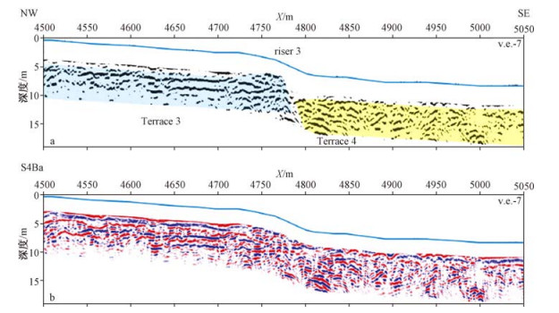
图 6 Christchurch city浅层地表二维雷达图像[26]
Figure 6. The profiles of GPR in Christchurch city

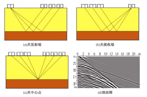
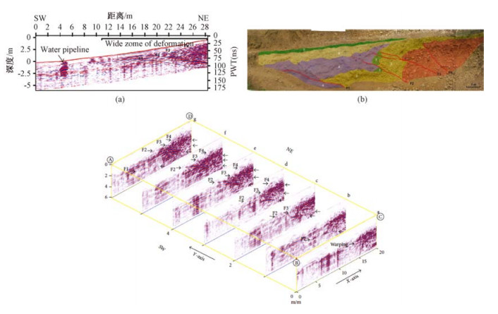
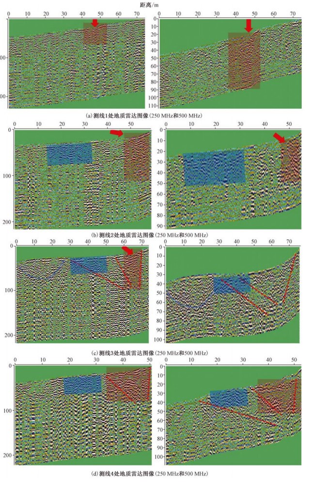
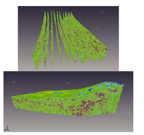
图 7 Sandhwal Village地区处理后频率为200 MHz的2D和3D地质雷达图像[34]
Figure 7. Processed 2D and 3D GPR profiles collected using 200 MHz antenna across the HF2 scarp at Sandhwal Village
-
[1] Zhao W K, Emanuele F, Sara T L, et al. Improved high-resolution GPR imaging and characterization of prehistoric archaeological features by means of attribute analysis[J]. Journal of Archaeological Science, 2015, 54: 77~85. doi: 10.1016/j.jas.2014.11.033 [2] Böniger* U, Tronicke J. Improving the interpretability of 3D GPR data using target-specific attributes: Application to tomb detection[J]. Journal of Archaeological Science, 2010, 37: 672~679. doi: 10.1016/j.jas.2010.01.013 [3] Hiroko O, Youngjoo K, Toru T. Depositional and erosional architectures of gravelly braid bar formed by a flood in the Abe River, central Japan, inferred from a three-dimensional ground-penetrating radar analysis[J]. Sedimentary Geology, 2015, 324: 32~46. doi: 10.1016/j.sedgeo.2015.04.008 [4] Li X J, Hu Z Q, Li S C, et al. Anomalies of mountainous mining paddy in western China[J]. Soil & Tillage Research, 2015, 145: 10~19. http://www.sciencedirect.com/science/article/pii/S0167198714001585 [5] Mercedes S, Higinio G G, Henrique L, et al. Uncertainty evaluation of the 1 GHz GPR antenna for the estimation of concrete asphalt thickness[J]. Measurement, 2013, 46: 3032~3040. doi: 10.1016/j.measurement.2013.06.022 [6] Arias P, Armesto J, Capua D D, et al. Digital photogrammetry, GPR and computational analysis of structural damages in a mediaeval bridge[J]. Engineering Failure Analysis, 2007, 14: 1444~1457. doi: 10.1016/j.engfailanal.2007.02.001 [7] Brosten T R, Bradford J H, McNamara J P, et al. Estimating 3D variation in active-layer thickness beneath arctic streams using ground-penetrating radar[J]. Journal of Hydrology, 2009, 73: 479~486. http://www.sciencedirect.com/science/article/pii/S0022169409003102 [8] Andrea B. Water content evaluation in unsaturated soil using GPR signal analysis in the frequency domain[J]. Journal of Applied Geophysics, 2010, 71: 26~35. doi: 10.1016/j.jappgeo.2010.03.001 [9] Pitambar P, Parkash B, Awasthi A K, et al. Concealed thrusts in the Middle Gangetic plain, India: A ground penetrating radar study proves the truth against the geomorphic features supporting normal faulting[J]. Journal of Asian Earth Sciences, 2011, 40: 315~325. doi: 10.1016/j.jseaes.2010.06.012 [10] Malik J N, Shah A A, Sahoo A K, et al. Active fault, fault growth and segment linkage along the Janauri anticline (frontal foreland fold), NW Himalaya, India[J]. Tectonophysics, 2010, 483: 327~343. doi: 10.1016/j.tecto.2009.10.028 [11] Mike D, Adam O, Dan C. Ground penetrating radar as a means of studying palaeofault scarps in a deeply weathered terrain, southwestern Western Australia[J]. Journal of Applied Geophysics, 2010, 72: 92~101. doi: 10.1016/j.jappgeo.2010.07.005 [12] Liberty L, Hemphill-Haley M A, Madin I P. The Portland Hills Fault: Uncovering a hidden fault in Portland, Oregon using high-resolution geophysical methods[J]. Tectonophysics, 2003, 368: 89~103. doi: 10.1016/S0040-1951(03)00152-5 [13] 杨峰, 彭苏萍.地质雷达探测原理与方法研究[M].北京:科学出版社, 2006.YANG Feng, PENG Su-ping. Principles and Methods of Ground penetrating radar[M]. Beijing: Sciences Press, 2006. [14] 曾昭发, 刘四新, 冯晅, 等.探地雷达原理与应用[M].北京:电子工业出版社, 2010.ZENG Zhao-fa, LIU Si-xin, FENG Xuan, et al. The principle and application of Ground Penetrating Radar[M]. Beijing: Electronics Industry Press, 2010. [15] Fisher E, McMechan G A, Annan A P. Acquisition and processing of wide-aperture ground penetrating radar data[J]. Geophysics, 1992, 57: 495. doi: 10.1190/1.1443265 [16] Grasmueck M. 3-D ground-penetrating radar applied to fracture imaging in gneiss[J]. Geophysics, 1996, 61: 1050~1064. doi: 10.1190/1.1444026 [17] 李树德.活动断层分段研究[J].北京大学学报:自然科学版, 1999, 35(6):768~773. http://www.cnki.com.cn/Article/CJFDTOTAL-BJDZ199906006.htmLI Shu-de. Study on segmentation of active faults[J]. Act a Scicentiarum Naturalum Universitis Pekinesis, 1999, 35(6): 768~773. http://www.cnki.com.cn/Article/CJFDTOTAL-BJDZ199906006.htm [18] 徐锡伟.活动断层、地震灾害与减灾对策问题[J].震灾防御技术, 2006, 1(1):7~13. doi: 10.11899/zzfy20060102XU Xi-wei. Active faults, associated earthquake disaster distribution and policy for disaster reduction[J]. Technology for Earthquake Disaster Prevention, 2006, 1(1): 7~13. doi: 10.11899/zzfy20060102 [19] 沈建文, 蔡长青.地震危险性分析与抗震设防标准的确定[J].地震工程与工程振动, 1997, 17(2):27~36. http://www.cnki.com.cn/Article/CJFDTOTAL-DGGC702.004.htmSHEN Jian-wen, CAI Chang-qing. Seismic hazard analysis and earthquake resistant level[J]. Earthquake Engineering and Engineering Vibration, 1997, 17(2): 27~36. http://www.cnki.com.cn/Article/CJFDTOTAL-DGGC702.004.htm [20] Audrua J C, Banob M, Beggc J, et al. GPR investigations on active faults in urban areas: The Georisc-NZ project in Wellington, New Zealand[J]. Earth and Planetary Sciences. 2001, 333: 447~454. http://www.academia.edu/3381673/GPR_investigations_on_active_faults_in_urban_areas_the_Georisc-NZ_project_in_Wellington_New_Zealand [21] Slater L, Niemi T M. Ground-penetrating radar investigation of active faults along the Dead Sea Transform and implications for seismic hazardswithin the city of Aqaba, Jordan[J]. Tectonophysics, 2003, 368: 33~50. doi: 10.1016/S0040-1951(03)00149-5 [22] Rasheda M, Kawamuraa D, Nemotoa H, et al. Ground penetrating radar investigations across the Uemachi fault, Osaka, Japan[J]. Journal of Applied Geophysics, 2003, 53: 63~75. doi: 10.1016/S0926-9851(03)00028-4 [23] Rasheda M, Kawamuraa D. High-resolution shallow seismic and ground penetrating radarinvestigations revealing the evolution of the Uemachi Fault system, Osaka, Japan[J]. The Island Arc, 2004, 13: 144~156. doi: 10.1111/iar.2004.13.issue-1 [24] Libertya L M, Hemphill-Haley M A, Madinc I P. The Portland Hills Fault: uncovering a hidden fault in Portland, Oregon using high-resolution geophysical methods[J]. Tectonophysics, 2003, 368: 89~103. doi: 10.1016/S0040-1951(03)00152-5 [25] khorsandi A, Abdali M, Miyata T, et al. Application of GPR Method Due to Active Faults Determination in Urban Area, Case Study: North Shahre Ray Fault, South of Tehran, Iran[C]. 2011 International Conference on Environment Science and Engineering, 2011. [26] Carpentier S F, Green A G, Doetsch J, et al. Recent deformation of Quaternary sediments as inferred from GPR images and shallow P-wave velocity tomograms: Northwest Canterbury Plains, New Zealand[J]. Journal of Applied Geophysics, 2012, 81:2~15. doi: 10.1016/j.jappgeo.2011.09.007 [27] 薛建, 贾建秀, 黄航, 等.应用探地雷达探测活动断层[J].吉林大学学报(地球科学版), 2008, 38(2):347~350.XUE Jian, JIA Jian-xiu, HUANG Hang, et al. Application of GPR in Active Fault Detection[J]. Journal of Jilin University(Earth Science Edition), 2008, 38(2):347~350. [28] 薛建, 黄航, 张良怀.探地雷达方法探测与评价长春市活动断层[J].物探与化探.2009, 33(1):63~66.XUE Jian, HUANG Hang, ZHANG Liang-huai. The Application of the GPR Method to Detecting and Estimating Active Faults in Changchun[J]. GEOPHYSICAL & GEOCHEM ICAL EXPLORATION. 2009, 33(1): 63~66. [29] 崔国柱, 李恩泽, 曾昭发.活动断层与地球物理方法[J].世界地质, 2003.22(2):185~190. http://www.cnki.com.cn/Article/CJFDTOTAL-SJDZ200302015.htmCUI Guo-zhu, LI Ee-ze, ZENG Zhao-fa. Active Fault and Geophysical Methods[J]. Global Geology, 2003, 22(2): 185~190. http://www.cnki.com.cn/Article/CJFDTOTAL-SJDZ200302015.htm [30] 李征西, 曾昭发, 李恩泽, 等.地球物理方法探测活动断层效果和方法最佳组合分析[J].吉林大学学报(地球科学版), 2005, 35:110~114. http://www.cnki.com.cn/Article/CJFDTOTAL-CCDZ2005S1023.htmLI Zheng-xi, ZENG Zhao-fa, LI Ee-ze, et al. The Function of Geophysical Method in Active Fault Detection and Discuss of Combining Methods[J]. Journal of Jilin University (Earth Science Edition). 2005, 35: 109~224. http://www.cnki.com.cn/Article/CJFDTOTAL-CCDZ2005S1023.htm [31] 李建军, 张军龙.探地雷达在探测潜伏活动断层中的应用[J].地震, 2015, 35(4):83~89.LI Jian-jun, ZHANG Jun-long. Application of GPR in Surveying Underlied Active Faults[J]. EARTHQUAKE, 2015, 35(4): 83~89. [32] Salvi S, Cinti F R, Colini L, et al. Investigation of the active Celano-L'Aquila fault system, Abruzzib(central Apennines, Italy) with combined ground-penetrating radarand palaeoseismic trenching[J]. Geophys. J. Int. 2003, 155: 805~811. doi: 10.1111/gji.2003.155.issue-3 [33] Anderson K B, Spotila J A, Hole J A. Application of geomorphic analysis and ground-penetrating radar to characterization of paleoseismic sites in dynamic alluvial environments: an example from southern California[J]. Tectonophysics, 2003, 368: 25~32. doi: 10.1016/S0040-1951(03)00148-3 [34] Malik J N, Kumar A, Satuluri S, et al. Ground-Penetrating Radar Investigations along Hajipur Fault: Himalayan Frontal Thrust—Attempt to Identify Near Subsurface Displacement, NWHimalaya, India[J]. International Journal of Geophysics, 2012. https://www.hindawi.com/journals/ijge/2012/608269/abs/ [35] Cahit C Y, Erhan A, Maksim B, et al. Application of GPR to normal faults in the Buyuk Menderes Graben, western Turkey[J]. Journal of Geodynamics, 2013, 65: 218~227. doi: 10.1016/j.jog.2012.05.011 [36] Chow J, Angelier J, Hua J, et al. Paleoseismic event and active faulting:from ground penetrating radar and high-resolution seismic reflection profiles across the Chihshang Fault. eastern Taiwan[J]. Tectonophysics, 2001, 33: 241~259. http://www.sciencedirect.com/science/article/pii/S0040195100002778 [37] Dentith M A O, Clark D. Ground penetrating radar as a means of studying palaeofault scarps in a deeply weathered terrain, southwestern Western Australia[J]. Journal of Applied Geophysics, 2010, 72: 92~101. doi: 10.1016/j.jappgeo.2010.07.005 [38] Ercoli M, Pauselli C, Frigeri A, et al. 2D AND 3D GROUND PENETRATING RADAR (GPR) CAN IMPROVE PALEOSEISMOLOGICAL RESEARCHES: AN EXAMPLE FROM THE MT. VETTORE FAULT (CENTRAL APPENNINES, ITALY)[C], GNGTS 2011. [39] Ercoli M, Pauselli C, Frigeri A, et al. 2D-3D GPR signature of shallow faulting in the Castelluccio di Norcia basin (Central Italy)[C]. EGU General Assembly, 2012. [40] Gross R, Green A, Holliger K, et al. Shallow geometry and displacements on the San Andreas Fault near Point Arena based on trenching and 3-D georadar surveying[J]. GEOPHYSICAL RESEARCH LETTERS 2002, 29. http://adsabs.harvard.edu/abs/2002GeoRL..29t..34G [41] Cristina P, Costanzo F, Alessandro F, et al. Ground penetrating radar investigation to study active faults in the Norcia Basin (central Italy)[J]. Journal of Applied Geophysics, 2010, 72: 39~45. doi: 10.1016/j.jappgeo.2010.06.009 [42] 张迪, 李家存, 吴中海, 等.探地雷达在探测玉树走滑断裂带活动性中的初步应用[J].地质通报, 2015, 34(1):204~216.ZHANG Di, LI Jia-cun, WU Zhong-hai, et al. A preliminary application of ground penetrating radar to the detection of active faults along Yushu strike-slip faulted zone. Geological Bulletin of China, 2015, 34(1): 204~216. [43] 栗毅, 黄春琳, 雷文太.探地雷达理论与应用[M].北京:科学出版社, 2011.LI Yi, HUANG Chun-lin, LEI Wen-tai. Ground Penetrating Radar: Theory and Applications[M]. Beijing: Sciences Press, 2011. [44] Millard S G, Shaw M R, Giannopoulos A, et al. Modeling of subsurface pulsed radar for nondestructive testing of structures[J]. ASCE J Mater Civil Eng 1998, 10: 96~188. doi: 10.1061/%28ASCE%290899-1561%281998%2910%3A3%28188%29 [45] Maurizio E, Cristina P, Alessandro F, et al. "Geophysical paleoses-mology" through high resolution GPR data: A case of shallow faulting imaging in Central Italy[J]. Journal of Applied Geophysics, 2013, 90: 27~40. doi: 10.1016/j.jappgeo.2012.12.001 [46] Green A G, Gross R, Holliger K, et al. Results of 3-D georadar surveying and trenching the San Andreas fault near its northern landward limit[J]. Tectonophysics, 2003, 368: 7~23. doi: 10.1016/S0040-1951(03)00147-1 [47] Gross R, Green A G, Horstmeyer H, et al. 3-D georadar images of an active fault: efficient data acquisition, processing and interpretation strategies[J]. Subsurface Sensing Technologies and Applications, 2003, 4 (1): 19~40. doi: 10.1023/A:1023059329899 [48] Vanneste K, Verbeeck K, Petermans T. Pseudo-3D imaging of a low-slip-rate active normal fault using shallow geophysical methods: the Geleen fault in the Belgian Mass River valley[J]. Geophysics, 2008, 73 (1): B1~B9. http://adsabs.harvard.edu/abs/2008Geop...73B...1V [49] McClymont A F, Green A G, Kaiser A, et al. Shallow fault segmentation of the Alpine fault zone, New Zealand revealed from 2-and 3-D GPR surveying[J]. Journal of Applied Geophysics, 2010, 70 (4): 343~354. doi: 10.1016/j.jappgeo.2009.08.003 [50] Carpentier S F A, Green A G, Langridge R. et al. Flower structures and Riedel shears at a step over zone along the Alpine Fault (New Zealand) inferred from 2-D and 3-D GPR images[J]. Journal of Geophysical Research, 2012:117. doi: 10.1029/2011JB008749/full#footer-citing -

 下载:
下载:


图(10)
计量
- 文章访问数: 460
- HTML全文浏览量: 221
- PDF下载量: 29
- 被引次数: 0
